Method of manufacturing three dimensional image display device

a three-dimensional image and display device technology, applied in the manufacture of electrode systems, instruments, electric discharge tubes/lamps, etc., can solve the problems of gap after manufacturing, difficulty in bringing the lenticular lens into complete contact, and gap formation. to achieve the effect of maintaining the accuracy of the gap

Inactive Publication Date: 2011-10-18
KK TOSHIBA
View PDF8 Cites 29 Cited by
  • Summary
  • Abstract
  • Description
  • Claims
  • Application Information

AI Technical Summary

Benefits of technology

[0014]The present invention aims to provide a method of manufacturing a three dimensional image display device capable of maintaining gap accuracy between pixels and a lens.

Problems solved by technology

In a process of mounting a lenticular lens on a display panel, it is so difficult to bring the lenticular lens into complete contact with the display panel that a gap may be formed therebetween.
Even when a display panel and a lenticular lens are brought into complete contact with each other, deformation due to their own weights, partial pressurization from outside, ambient temperature rise and the like may cause a gap after the manufacturing.
If such a gap is larger than an allowable range (for example, a range of a desired value plus or minus several tens of μm), an error in the viewing angle falls outside an allowable range.
This method, however, causes a phenomenon in which an internal pressure in an enclosed space in the display device becomes higher than a pressure in the reduced pressure atmosphere in which the bonding is performed.
This condition facilitates the generation of a gap between the display panel and the lens plate because of deformation due to their own weights, partial pressurization from outside, ambient temperature rise and the like, and thereby makes it difficult to maintain accuracy of a gap between the display panel and the lens plate, i.e., gap accuracy between the pixels and the lens.

Method used


Image

  • Method of manufacturing three dimensional image display device
  • Method of manufacturing three dimensional image display device
  • Method of manufacturing three dimensional image display device

Examples


first embodiment

[0033]A first embodiment of the present invention will be described with reference to FIGS. 1 to 9.

(Three Dimensional Image Display Device)

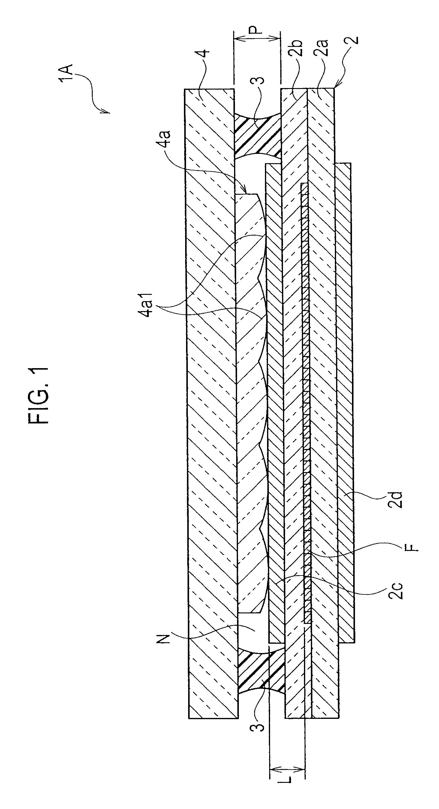
[0034]As shown in FIG. 1, a three dimensional image display device (hereinafter, simply called a display device) 1A according to the first embodiment of the present invention includes a display panel 2, and a lens plate 4 that is provided above the display panel 2 with an adhesive member 3 interposed therebetween and has a lenticular lens 4a on its display panel 2 side. An enclosed space N is an internal space formed by the display panel 2, the adhesive member 3 and the lens plate 4, and is hermetically sealed. The enclosed space N is in a hermetically sealed state having an internal pressure lower than the atmospheric pressure.

[0035]The display panel 2 includes a first substrate 2a that is an array substrate or the like and serves as a back surface substrate; and a second substrate 2b which serves as a front surface substrate. Within a plane of ...

second embodiment

[0068]A second embodiment according to the present invention will be described with reference to FIGS. 10 and 11.

[0069]The second embodiment of the present invention is basically the same as the first embodiment. For this reason, the second embodiment will be described only in points different from the first embodiment. Moreover, the description on part of the second embodiment is omitted if the part is the same as the first embodiment.

[0070]In the second embodiment of the present invention, an adhesive member 3 formed in a continuous frame shape having an application height higher than a final adhesive thickness (height) P of a display device 1A is provided with lower portions (recessed portions) each having an application height lower than the final adhesive thickness P. Moreover, the adhesive member 3 is formed so that the lower portions can be filled with the adhesive member 3 with its surface tension and viscosity after the bonding. Here, the width and number of the lower porti...

third embodiment

[0073]A third embodiment according to the present invention will be described with reference to FIGS. 12 to 15.

[0074]The third embodiment of the present invention is basically the same as the first embodiment. For this reason, the third embodiment will be described only in points different from the first embodiment. Moreover, the description on part of the third embodiment is omitted if the part is the same as the first embodiment.

[0075]In the third embodiment of the present invention, an adhesive member 3 is applied to a display panel 2 to form a discontinuous frame having an application height higher than a final adhesive thickness (height) P of a display device 1A, and is formed so that such discontinuous portions can be filled with the adhesive member 3 with its surface tension and viscosity after the bonding. Here, the width and number of the discontinuous portions are adjusted suitably according to the size of the display panel 2, a material used as the adhesive member 3, and ...


PUM

PropertyMeasurementUnit
heightaaaaaaaaaa
widthaaaaaaaaaa
heightaaaaaaaaaa

Abstract

A method of manufacturing a three dimensional image display device includes: applying an adhesive member to any one of a lens plate and a display panel so as to form a continuous frame having an application height higher than a separation distance between the lens plate and the display panel in a bonding complete state; measuring the application height of the adhesive member; figuring out a volume of an enclosed space, which is formed by the display panel, the adhesive member and the lens plate, by using a lowest application height of the adhesive member, and figuring out a bonding pressure leading to obtaining of a necessary internal pressure in the enclosed space, by using the figured-out volume of the enclosed space; and bonding the lens plate and the display panel together with the adhesive member in a reduced pressure atmosphere with the figured-out bonding pressure.

Description

CROSS REFERENCE OF THE RELATED APPLICATION[0001]This application is based on and claims the benefit of priority from Japanese Patent Application No. 2008-180040, filed on Jul. 10, 2008; the entire contents of which are incorporated herein by reference.BACKGROUND OF THE INVENTION[0002]1. Field of the Invention[0003]The present invention relates to a method of manufacturing a three dimensional image display device.[0004]2. Description of the Related Art[0005]Flat panel display devices are generally used as display panels for three dimensional image display devices. Such flat panel display devices include: a liquid crystal display panel (LCD) which controls the intensity of light by utilizing the orientation of liquid crystals, a plasma display panel (PDP) in which ultraviolet rays of plasma discharges cause phosphors to emit light, a field emission display panel (FED) in which electron beams of a field emission electron emitter cause phosphors to emit light, and an electron emission d...

Claims


Application Information

Patent Timeline
Patent Type & Authority Patents(United States)
IPC IPC(8): H01J9/00B32B37/10B29C65/54
CPCG02F1/133526H01J9/241H01J11/10H01J29/89H04N13/0404H01J31/123G02F2202/28H04N2213/001H01J2211/44H01J2329/897H04N13/0425H01J9/20H04N13/305H04N13/327
Inventor MIYAUCHI, TAKASHIMIYAZAKI, KENTARO
Owner KK TOSHIBA
Why Eureka
Try Eureka