
Clamping device with reinforced clamping lugs

Active Publication Date: 2011-10-25
ESTAB CAILLAU SARL
View PDF21 Cites 8 Cited by
  • Summary
  • Abstract
  • Description
  • Claims
  • Application Information

AI Technical Summary

Benefits of technology

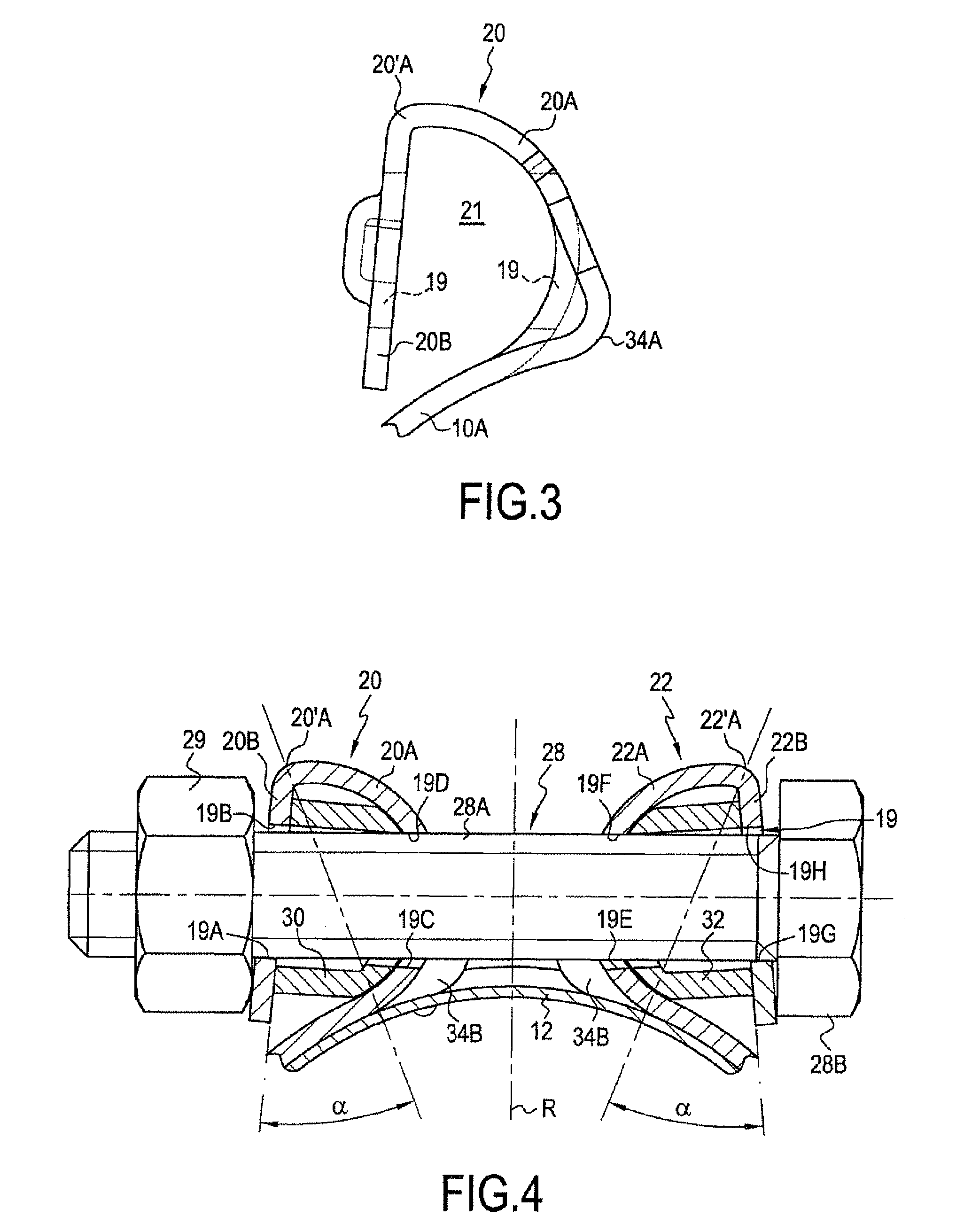
[0009]The fact that the connection portion is curved facilitates good distribution of the tightening forces. The zone of locally increased curvature at the base of the connection portion has been subjected to considerable work-hardening and is thus not deformed very much during tightening. In addition, that fact that both of the lugs situated facing each other have protuberances of this type makes it possible locally to reduce the width of the slot so as to bring the belt closer to a continuous, looped belt.
[0011]The presence of said reinforcement means makes it possible to push back the plastic deformation limit of the lugs and to avoid the effects of flattening due to said lugs bending.
[0012]The reinforcement means are preferably disposed in the space formed between the connection portion and the tightening wall and preserve the dimensions of that space, i.e. they prevent the tightening wall and the connection portion from coming too close together, which would result in the lug flattening onto itself.
[0015]In a second embodiment, the reinforcement means advantageously comprise a spacer formed in one piece with the lug. This embodiment offers the advantage of avoiding manufacturing and handling an additional part.

Problems solved by technology

Even though such collars are generally satisfactory, it has been observed that, for certain demanding applications, the tightening might lose some of its effectiveness because, firstly, the co-operation between the tightening means, in particular means having bolts, might not take place in the desired manner, in particular due to the bolts not being guided properly, and, secondly, the lugs might bend under the effect of the tightening forces.

Method used


Image

  • Clamping device with reinforced clamping lugs
  • Clamping device with reinforced clamping lugs
  • Clamping device with reinforced clamping lugs

Examples


Embodiment Construction

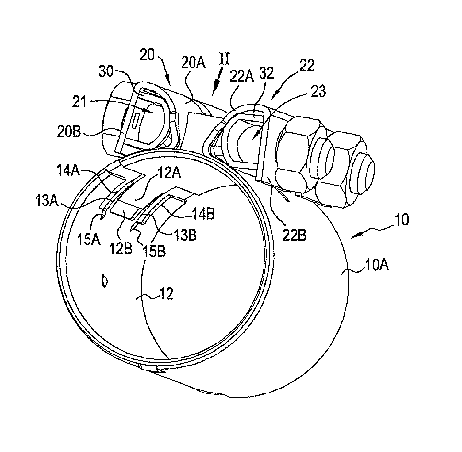
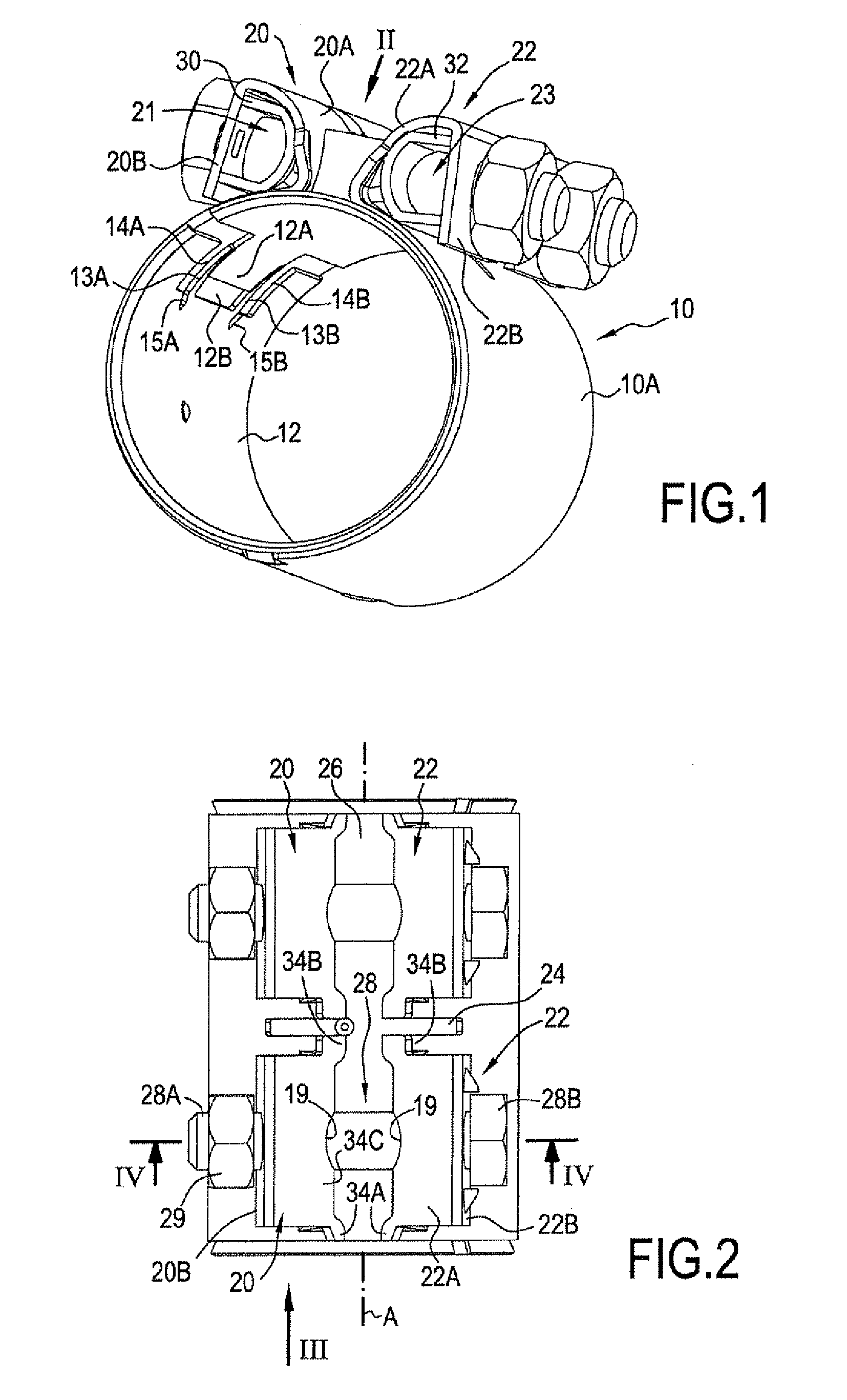
[0042]The clamping device of FIGS. 1 and 2 comprises a collar 10 inside which a sealing ring 12 is disposed for the purpose of surrounding the facing ends of two smooth tubes, coupled together in leaktight manner by means of said device. The sealing ring can be implemented in the manner known by Patent Application EP 1 181 477. However, advantageously, as shown in FIG. 1, its ends are provided respectively with a male shaped portion 12A and with a female shaped portion 12B, which receives the male shaped portion during tightening and which is defined between two contact tabs 13A and 13B. The leaktight contact is established on the contact edges of the contact tabs 13A and 13B that can be deflected during the tightening so as to facilitate penetration of the male shaped portion into the female shaped portion. Setbacks 14A and 14B facilitating this deflecting are advantageously provided on the sides of the tabs 13A and 13B that face the notch 12B that forms the female shaped portion. ...


PUM


Abstract

Disclosed is a clamping device including a collar having at least one pair of projecting lugs and tightening means co-operating with said lugs. Each lug of a pair is equipped with reinforcement means suitable for opposing deformation of said lugs under the action of the tightening means. Each lug has a connection portion via which it is connected to a belt portion of the collar, which connection portion is upstanding relative to said belt portion, and a tightening wall, with which the tightening means come into engagement and which is folded back towards the belt portion. A space is formed between the connection portion and the tightening wall.

Description

BACKGROUND OF THE INVENTION[0001]The present invention relates to a clamping device comprising a collar, suitable for being disposed around objects to be clamped, and having at least one pair of projecting lugs, the device further comprising tightening means suitable for co-operating with lugs of said pair to move them relative to each other in a manner such as to clause the diameter of the collar to decrease.[0002]In particular, the tightening means are of the nut and bolt type. Collars of this type, e.g. for clamping together two smooth tubes disposed end-to-end, are known from Patent Application EP 1 181 477. Conventionally, the collar includes a belt portion relative to which the two lugs serving for tightening are upstanding. The belt portion is disposed around the object(s) to be clamped, and the lugs, which for raised lips, are disposed facing each other to define a slot between them of width that is decreased during tightening.[0003]In the collar described in the above-menti...

Claims


Application Information

Patent Timeline
IPC IPC(8): F16B2/06
CPCF16B2/065F16L21/065F16L33/04F16L21/005Y10T24/1412Y10T24/1443Y10T24/1441F16L21/06F16B2/06
Inventor RIGOLLET, NICOLASPREVOT, FABRICEROINTRU, TONY
Owner ESTAB CAILLAU SARL
Learn More