Vacuum generating unit

a technology of vacuum generating unit and vacuum pump, which is applied in the direction of machines/engines, servomotors, transportation and packaging, etc., can solve the problem of inability to hold the workpi

Active Publication Date: 2011-10-25
SMC CORP
View PDF18 Cites 2 Cited by
  • Summary
  • Abstract
  • Description
  • Claims
  • Application Information

AI Technical Summary

Benefits of technology

[0009]A general object of the present invention is to provide a vacuum generating unit, which is capable of maintaining a negative pressure when the workpiece is being held, by allowing the vacuum port to communicate with atmosphere only at a positive pressure time when the negative pressure state is released or canceled.

Problems solved by technology

Further, in this type of vacuum generating unit, because attraction under suction of the workpiece is performed, whereupon the supplied amount of compressed air is reduced when the workpiece is in a held state, communication with the atmosphere results through the atmospheric pressure supply valve, which is in a valve open state, and thus holding of the workpiece cannot be performed.

Method used


Image

  • Vacuum generating unit
  • Vacuum generating unit
  • Vacuum generating unit

Examples


Embodiment Construction

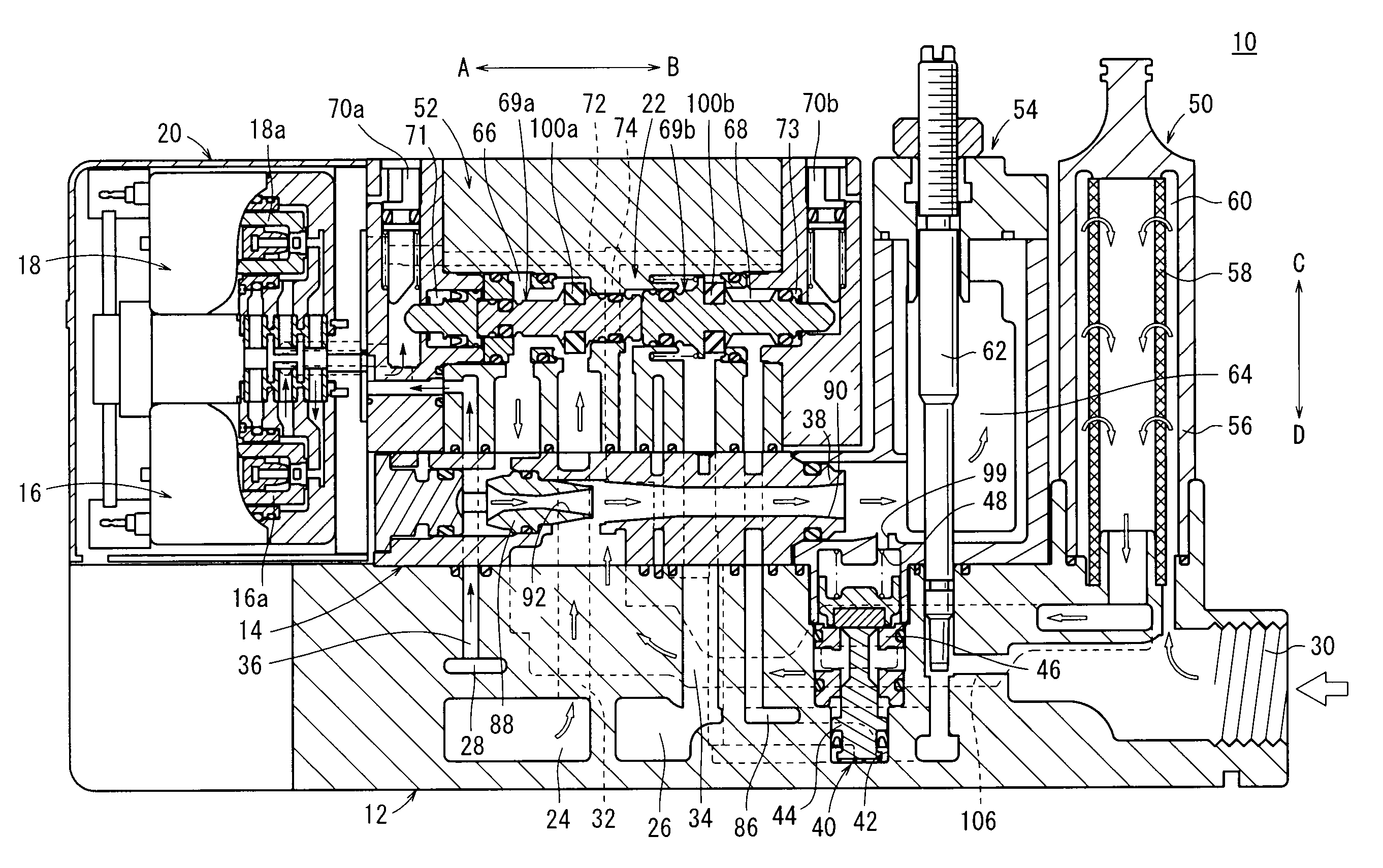
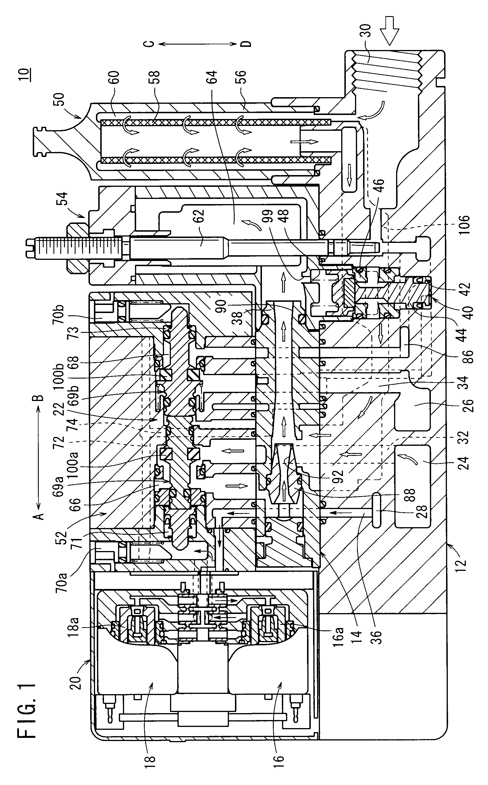
[0021]In FIG. 1, reference numeral 10 indicates a vacuum generating unit according to an embodiment of the present invention.

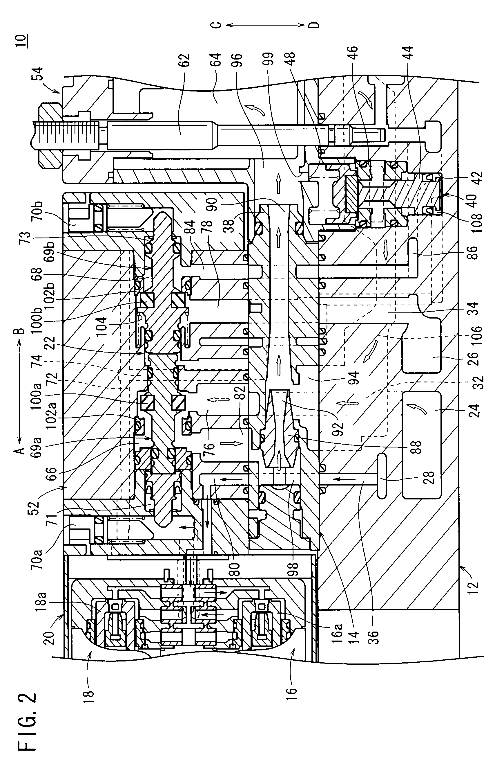
[0022]The vacuum generating unit 10, as shown in FIGS. 1 through 4, includes a main body 12 formed with a predetermined length, an ejector 14 connected to a top portion of the main body 12 and functioning as a vacuum generating mechanism, a solenoid valve section 20 disposed at a side portion of the ejector 14 and having a pilot supply valve 16 and a pilot vacuum breakage valve 18, and a switching valve section 22 disposed on an upper portion of the ejector 14, which is displaced under the supply of pilot air thereto, for switching between a vacuum generating condition in which a negative pressure is generated and a vacuum breakage condition in which the negative pressure is released to atmospheric pressure.

[0023]The main body 12 has a predetermined length in the longitudinal direction (the direction of arrows A and B), wherein on a side surface of the main bo...


PUM


Abstract

An ejector functioning as a vacuum generating mechanism is disposed in a main body constituting a vacuum generating unit, and an atmospheric air introducing valve is disposed between the ejector and a vacuum port. The atmospheric air introducing valve is brought into a valve closed state at times when a negative pressure is generated by the ejector under a condition in which a workpiece is held by the negative pressure generated by the ejector, whereby communication between the vacuum port and the atmosphere is blocked. On the other hand, at times when the vacuum is broken, in which the negative pressure state of the vacuum port is released, the atmospheric air introducing valve is brought into a valve open state, whereby the vacuum port communicates with the atmosphere.

Description

BACKGROUND OF THE INVENTION[0001]1. Field of the Invention[0002]The present invention relates to a vacuum generating unit, which supplies a negative pressure to a working device such as a suction pad or the like, and more specifically, to a vacuum generating unit having a solenoid valve section therein capable of switching between supplying and cutting off supply of the negative pressure.[0003]2. Description of the Related Art[0004]Conventionally, a vacuum generating unit has been known, which is used, for example, as a workpiece transport mechanism or as a positioning mechanism. In such a vacuum generating unit, a suction mechanism such as a suction pad or the like is connected to the unit main body, whereby under the action of a negative pressure which is supplied from the unit main body, a workpiece can be attracted under suction by means of the suction mechanism. In addition, transportation of the workpiece is carried out, in which the workpiece is displaced while maintaining th...

Claims


Application Information

Patent Timeline
Patent Type & Authority Patents(United States)
IPC IPC(8): F04F5/48
CPCF04F3/00F04F5/02Y10T137/86083F16B47/00F15B11/064F15B21/14
Inventor FUKANO, YOSHIHIROOSHIMA, MASAYUKI
Owner SMC CORP
Why Eureka
Try Eureka