Storm drain protector

a storm drain and protector technology, applied in the direction of sewage draining, separation process, filtration separation, etc., can solve the problems of high rate, easy clogging of storm drains, variable flow rate of storm drains,

Inactive Publication Date: 2011-10-25
RUEDA JOHN
View PDF142 Cites 51 Cited by
  • Summary
  • Abstract
  • Description
  • Claims
  • Application Information

AI Technical Summary

Problems solved by technology

Such a grating does not filter anything but the largest of debris and is easily clogged when such large materials amass and cover the opening.
Unfortunately, storm drains are subject to variable flow rates, with very high rates being common.
Although the Kent apparatus succeeds in preventing the passage of sediment and small debris that would otherwise bypass the grating, it is likely that such a fibrous mat would need to be continuously cleaned and would quickly clog in high flow situations or if left untended for any significant period of time.
Moreover, the Kent apparatus provides no method of filtering liquid contaminants, such as motor oil, that may commonly find their way to storm drains.
While the Sanguinetti device addresses the need to make such devices easily cleaned and installed, as with Kent, the Sanguinetti device has the disadvantage that it quickly becomes clogged and must be continuously cleaned to maintain flow into the drain.
Kent also does not address the problem of potential liquid pollutants.
As is shown by the foregoing art, despite a long felt need, none of the prior approaches to preventing sediment and debris from entering storm drains have been able to effectively filter such materials in a way that prevents the filtering apparatus from quickly becoming clogged in high flow situations.
Moreover, none of the prior approaches has been effective in substantially preventing liquid pollutants, such as motor oil, from passing into storm drains.

Method used


Image

  • Storm drain protector
  • Storm drain protector
  • Storm drain protector

Examples


first embodiment

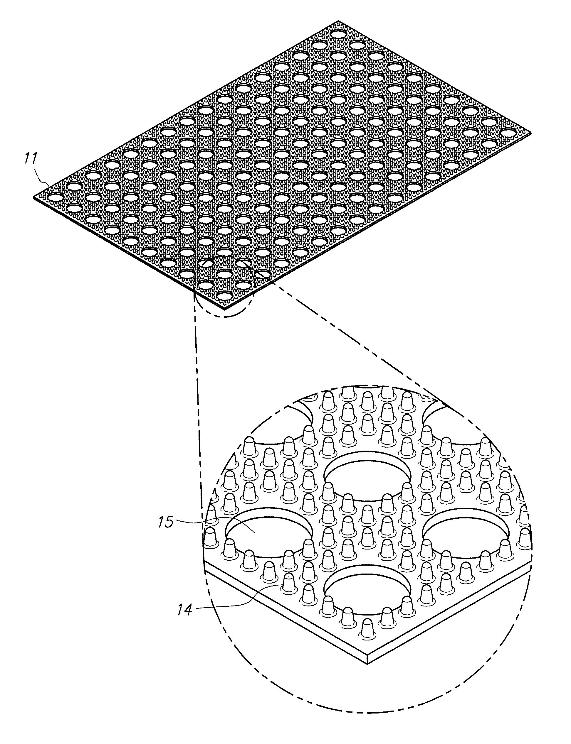
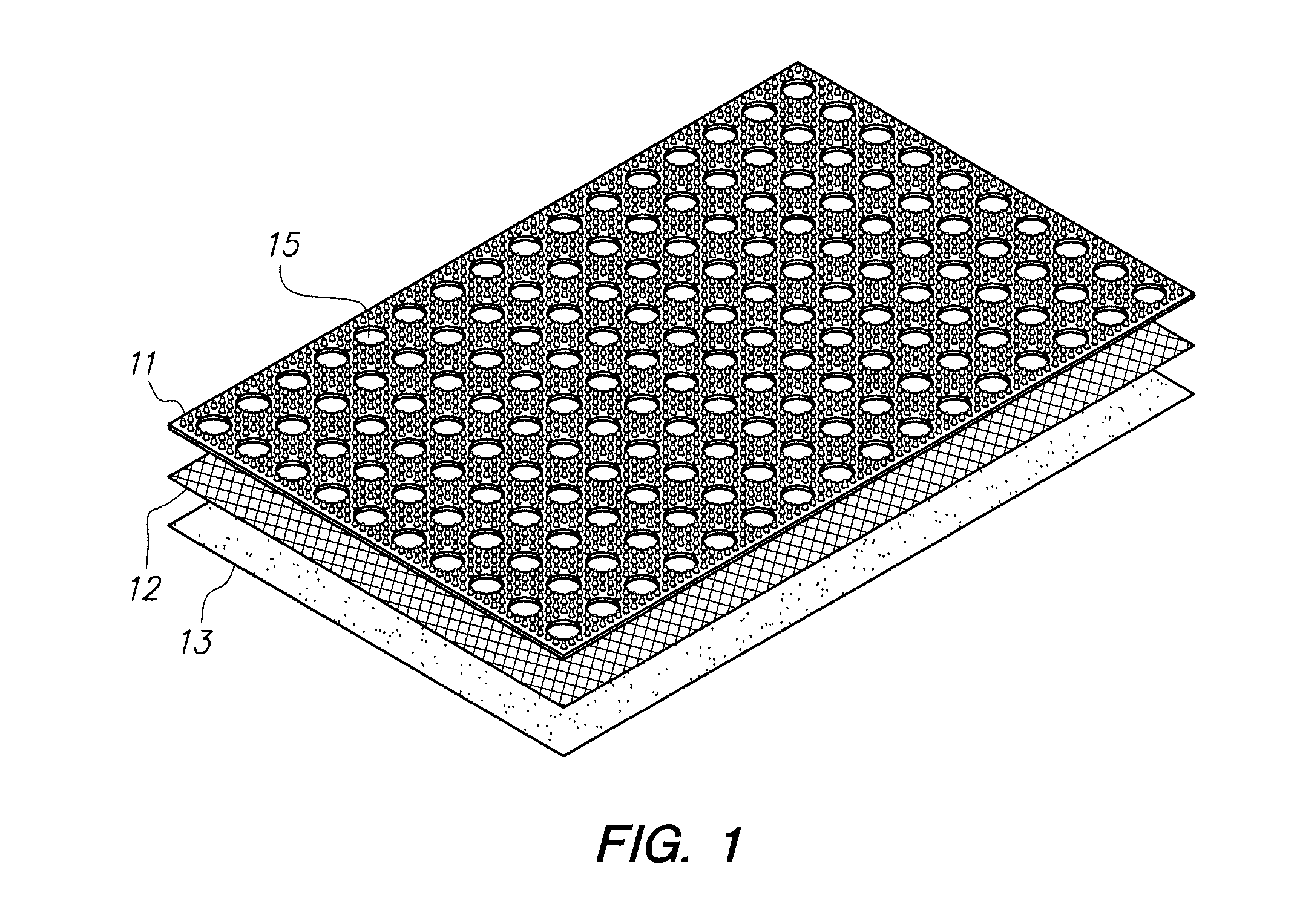
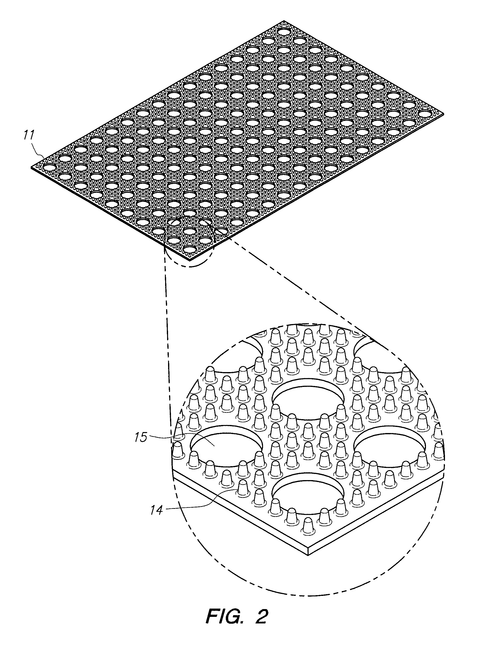
[0029]In a first embodiment, as shown in FIG. 1, the storm drain protector is rectangular and has three layers 11, 12, 13. The first or top layer 11, as shown in FIG. 2, is a rubber or extruded plastic mat having small (approximately a half inch tall) projections 14 and perforations 15 (approximately a half inch wide) over its entire surface area. The second or center layer 12 is composed of a screen or mesh, having apertures of approximately one-eighth of an inch or greater. The third or bottom layer 13 is composed of a lightweight and very dense felt material, having hydrophobic properties. These three layers are sewn together at the edges or otherwise fastened together and act as a single barrier that is laid over the conventional metal grating of a storm drain.

[0030]In operation, as shown in FIG. 3, water, having debris and sediment, flows horizontally toward the protector. Upon encountering the protector's edge, large debris and sediment 16 is blocked from moving horizontally o...

second embodiment

[0032]In a second embodiment, shown in FIG. 4, in addition to the top layer having small projections 22 and perforations 23, the mat also has small (approximately half inch wide) depressions 24. These depressions 24 serve as a trap into which may fall medium sized sediment particles that would otherwise flow through the perforations 23 and be filtered out by the middle or bottom layer. It is advantageous to trap such material on the surface of the mat so that it does not impede the flow of water through the other layers.

[0033]This embodiment also shows the perforations having an edge 25 that projects above the flat surface of the top layer 21. The edge 25 forms a further barrier to fine debris or sediment flowing into the perforations 23.

[0034]In the embodiment shown in FIG. 5, in addition to or in place of the multiple perforations 32 of the top layer 31, there is a large hole 33 in the top layer 31 at or near its center that is of relatively greater size, i.e., greater that four i...


PUM

PropertyMeasurementUnit
diameteraaaaaaaaaa
sizeaaaaaaaaaa
heightaaaaaaaaaa

Abstract

A storm drain protector with a top layer having a generally horizontal surface in which there is at least one hole that allows water to pass vertically through the surface. The horizontal surface also has several vertical projections emanating from the surface that permit the passage of water over the surface while impeding the passage of debris.

Description

REFERENCE TO RELATED APPLICATION[0001]This application claims the benefit of U.S. Provisional Patent Application No. 61 / 237,230, filed Aug. 26, 2009, the disclosure of which is incorporated herein.BACKGROUND OF THE INVENTION[0002]1. Field of the Invention[0003]This invention describes a storm drain protector used to filter storm water runoff of sediment and other debris so that such materials do not clog the drain, hinder flow or pollute the body of water to which such drains ultimately flow.[0004]2. Description of Related Art[0005]Storm drains, commonly located in roadways, parking lots or beside sidewalks, are ordinarily covered by a simple metal grating that serves the dual purpose of preventing large debris from entering the drain and providing a barrier for pedestrians and animals. Such a grating does not filter anything but the largest of debris and is easily clogged when such large materials amass and cover the opening. Where there is a potential for large amounts of sediment...

Claims


Application Information

Patent Timeline
Patent Type & Authority Patents(United States)
IPC IPC(8): E03F5/06
CPCE03F1/00E03F5/0404Y10T29/49826
Inventor RUEDA, JOHN
Owner RUEDA JOHN
Why Eureka
Try Eureka