Display system, display device, and program

a display device and display system technology, applied in the field of display devices and display systems, can solve the problems of difficult for users to determine whether the display device is in a normal mode or a power saving mode, and the display device does not recognize the line drawn, so as to achieve the effect of less power consumption and less power consumption

Inactive Publication Date: 2011-10-25
SEIKO EPSON CORP
View PDF8 Cites 45 Cited by
  • Summary
  • Abstract
  • Description
  • Claims
  • Application Information

AI Technical Summary

Benefits of technology

[0008]A first aspect of the present invention provides a display system comprising: a display device with a display surface; and an input device that is able to communicate with the display device, wherein: the input device comprises: a track detection unit that detects a track of points of contact between the input device operated by a user and the display surface; a writing unit that writes track data indicating the track detected by the track detection unit in a memory; and a sending unit that retrieves the track data from the memory and sends the track data to the display device; and the display device comprises: a position detection unit that detects positions on the display surface contacted by the input device and generates drawing data representing a line formed by points on the detected positions; an operation mode change unit that changes an operation mode of the display device from a position detection mode for causing the position detection unit to detect the positions to a position non-detection mode for not causing the position detection unit to detect the positions or vice versa; an instruction unit that, when the display device is in the position non-detection mode, instructs the input device to detect the track; a request unit that, when the operation mode of the display device is changed from the position non-detection mode to the position detection mode, requests the input device for the track data; a synthesizing unit that synthesizes the track data sent from the sending unit of the input device in response to the request from the request unit and drawing data generated by the position detection unit after the operation mode of the display device is changed to the position detection mode, to generate image data; and a display unit that displays an image represented by the image data generated by the synthesizing unit, on the display surface.

Problems solved by technology

This is because functions of the display device are not active during the process of returning from a power saving mode to a normal mode; accordingly, the display device does not recognize the line drawn during the process.
Such a situation may occur especially when a display device that uses cholesteric liquid crystal or electrophoresis is used.
This is because such a display device has a memory ability to maintain a displayed image even after the display device enters a power saving mode; namely, an image is displayed in the same way in both a normal mode to a power saving mode; accordingly, it is difficult for a user to determine whether the display device is in a normal mode or a power saving mode.

Method used


Image

  • Display system, display device, and program
  • Display system, display device, and program
  • Display system, display device, and program

Examples


modification 1

[0054

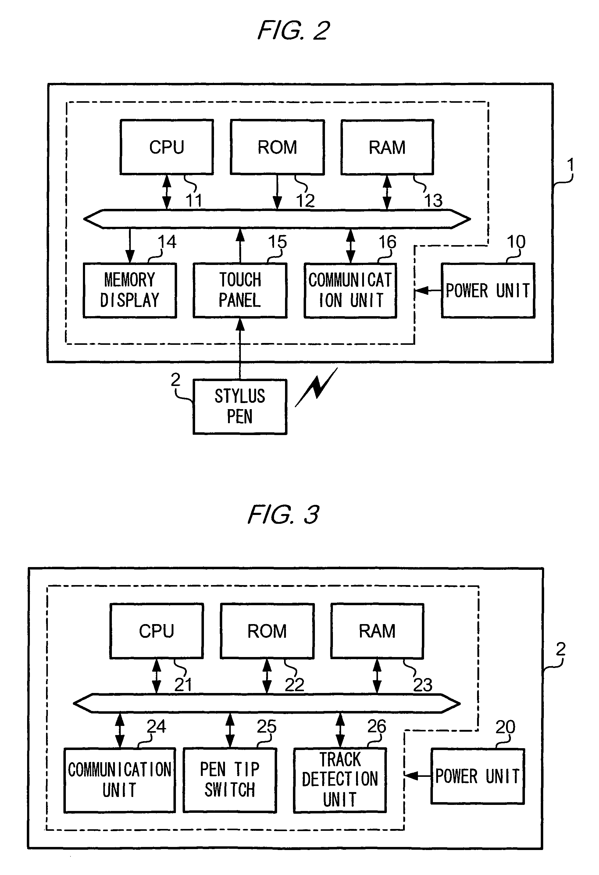
[0055]In the above embodiment, where track detection unit 26 optically detects a track of points of contact between stylus pen 2 and display surface S of touch panel 15, track detection unit 26 may be provided with a gyroscope for measuring angular velocity of stylus pen 2 used by a user, and detect a track of points of contact between stylus pen 2 and display surface S of touch panel 15 on the basis of angular velocity measured by the gyroscope. Alternatively, track detection unit 26 may be provided with an acceleration sensor for measuring acceleration of stylus pen 2 used by a user, and detect a track of points of contact between stylus pen 2 and display surface S of touch panel 15 on the basis of acceleration measured by the acceleration sensor. Track detection unit 26 may detect a track of points of contact between stylus pen 2 and display surface S of touch panel 15 in another method.

modification 2

[0056

[0057]In the above embodiment, where communication unit 16 of display device 1 and communication unit 24 of stylus pen 2 communicate data with each other wirelessly, they may be connected via a communication cable, and communicate data with each other according to USB (Universal Serial Bus).

modification 3

[0058

[0059]In the above embodiment, where CPU 21 of stylus pen 2 activates or deactivates track detection unit 26 in accordance with an instruction from display device 1, CPU 21 of stylus pen 2 may switch an operation mode of stylus pen 2 in accordance with an instruction from display device 1. For example, CPU 21 may switch an operation mode of stylus pen 2 to a track detection mode, on receipt of a notification from display device 1 that an operation mode of display device 1 is about to enter a position non-detection mode. The track detection mode is a mode in which power is supplied from power unit 20 to components of stylus pen 2 to enable the components to work. If an operation mode is changed to a track detection mode, and pen tip switch 25 is turned on, track detection unit 26 detects a track of points of contact between stylus pen 2 and display surface S of touch panel 15. Also, CPU 21 may switch an operation mode of stylus pen 2 to a track non-detection mode, on receipt of ...


PUM


Abstract

A display system having an input device that communicates with a display device. The input device being able to: detect a track of points of contact between the input device and the display surface; write the track data to a memory; and send the track data to the display device. The display device being able to: detect positions on the display surface contacted by the input device and generate a line formed by the detected positions; toggle between a position detection mode to a position non-detection mode; instruct the input device to detect the track it is in the position non-detection mode; request the track data from the input device when it toggles to the position detection mode; synthesize the track data from the input device and the drawing data to generate image data; and display the generated image data.

Description

[0001]The entire disclosure of Japanese Patent Application No. 2007-306192 filed on Nov. 27, 2007 is expressly incorporated by reference herein.BACKGROUND[0002]1. Technical Field[0003]The present invention relates to a technique of displaying a line drawn on a display surface by a user.[0004]2. Related Art[0005]A touch-panel-type display device is used, which returns to a normal mode from a power saving mode in which less power is consumed than in the normal mode, in response to a touch by a user to the display device. For example, JP-A-2001-325071 discloses a controller with a touch sensor for operating equipment provided in a car, which gets out of a sleep mode in which little electricity is used, in response to a touch to the touch sensor.[0006]When such a display device is used, if a user is unaware that the display device operates in a power saving mode, it is possible that the user will start drawing a line using a stylus pen, without waiting for the display device to return f...

Claims


Application Information

Patent Timeline
Patent Type & Authority Patents(United States)
IPC IPC(8): G06F3/041G06F3/038
CPCG06F1/3262G06F3/03545G06F3/0488G06F3/04883G06F2203/04106
Inventor NARUSAWA, ATSUSHI
Owner SEIKO EPSON CORP
Why Eureka
Try Eureka