
Slider, integrated slider, and hybrid storage device

a hybrid storage device and slider technology, applied in the field of sliding, can solve the problems of difficult downsizing of sliders, inability to maintain head carrier alignment, inability to track the speed of the slider, etc., and achieve the effect of reducing the weight of sliders, and effective leading the swirl of evanescent ligh

Inactive Publication Date: 2011-10-25
SHARP KK
View PDF9 Cites 0 Cited by
  • Summary
  • Abstract
  • Description
  • Claims
  • Application Information

AI Technical Summary

Benefits of technology

[0017]The present invention was made in view of the foregoing problem. An object of the present invention is to provide a slider, an integrated slider, and a hybrid storage device, each capable of increasing access speed of the slider by downsizing the slider substantially as small as semiconductor laser.
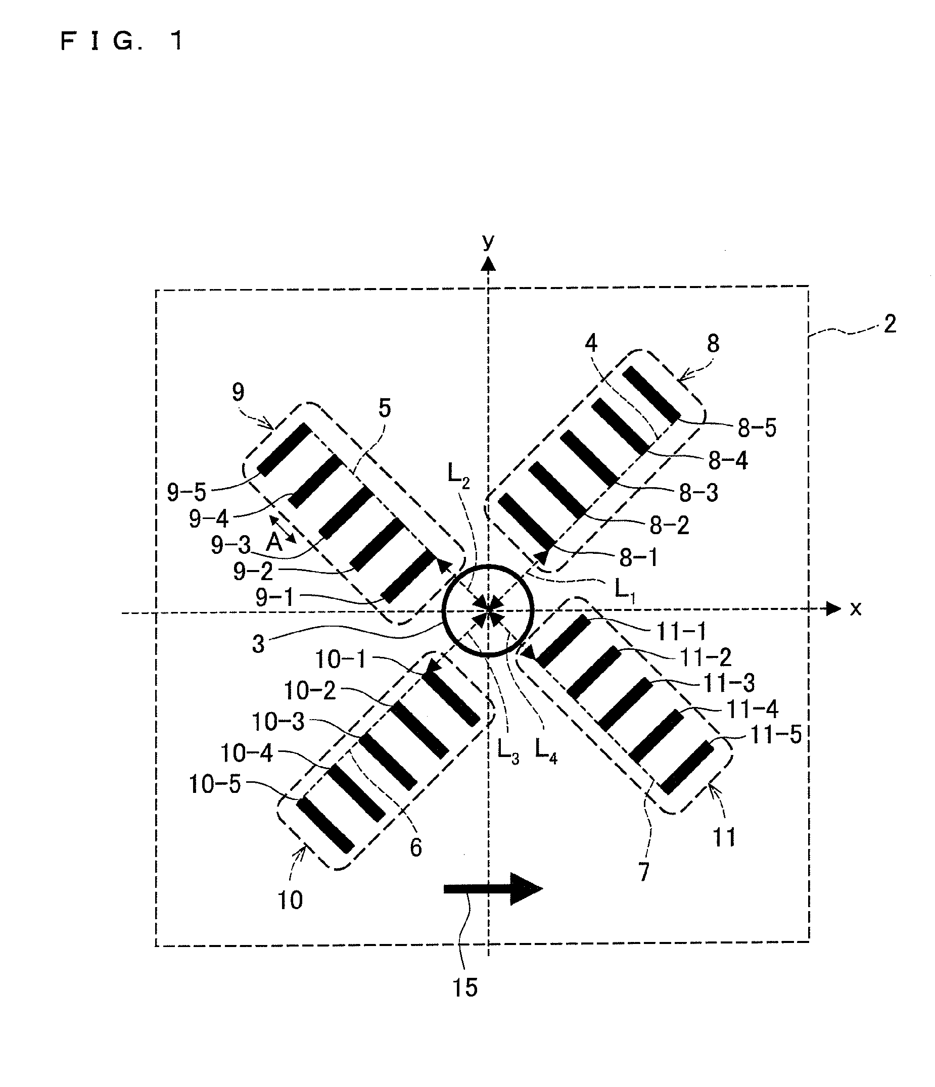
[0019]This allows converting linearly polarized light irradiated to the surface of the metal film into circularly polarized light. In other words, this allows converting the flow of light energy irradiated to the surface of the metal film into evanescent light with use of the periodic grooves and generating swirl of evanescent light with the opening at the center. Further, it is possible to make the size of the swirl smaller than the resolution limit of light, i.e. the wavelength of light.
[0021]Further, since the opening is formed at the center of the periodic grooves, it is possible to effectively lead the swirl of the evanescent light to the opening.
[0022]Consequently, an optical component for converting linearly polarized light into circularly polarized light is unnecessary, which allows downsizing the slider. This allows reducing the weight of the slider, which allows reducing moment of inertia of the slider. This allows increasing access speed of the slider.

Problems solved by technology

It is generally known that larger thermal fluctuation constant results in instability of magnetic information, such as accidental spin inversion.
However, a slider used in a hard disc drive is getting smaller year after year.
That is, the integrated slider with the above configuration where the optical lens and the wavelength plate are combined has a problem that it is difficult to downsize the slider and that there is a possibility that the slider gets larger.

Method used


Image

  • Slider, integrated slider, and hybrid storage device
  • Slider, integrated slider, and hybrid storage device
  • Slider, integrated slider, and hybrid storage device

Examples


Embodiment Construction

[0057]One embodiment of the present invention is described below with reference to FIGS. 1-14.

[0058][Outline of Slider]

[0059](1-1. Metal Plane of Slider)

[0060]An explanation is made below as to the surface of a metal film 2 on a surface of a slider 20 with reference to FIG. 1.

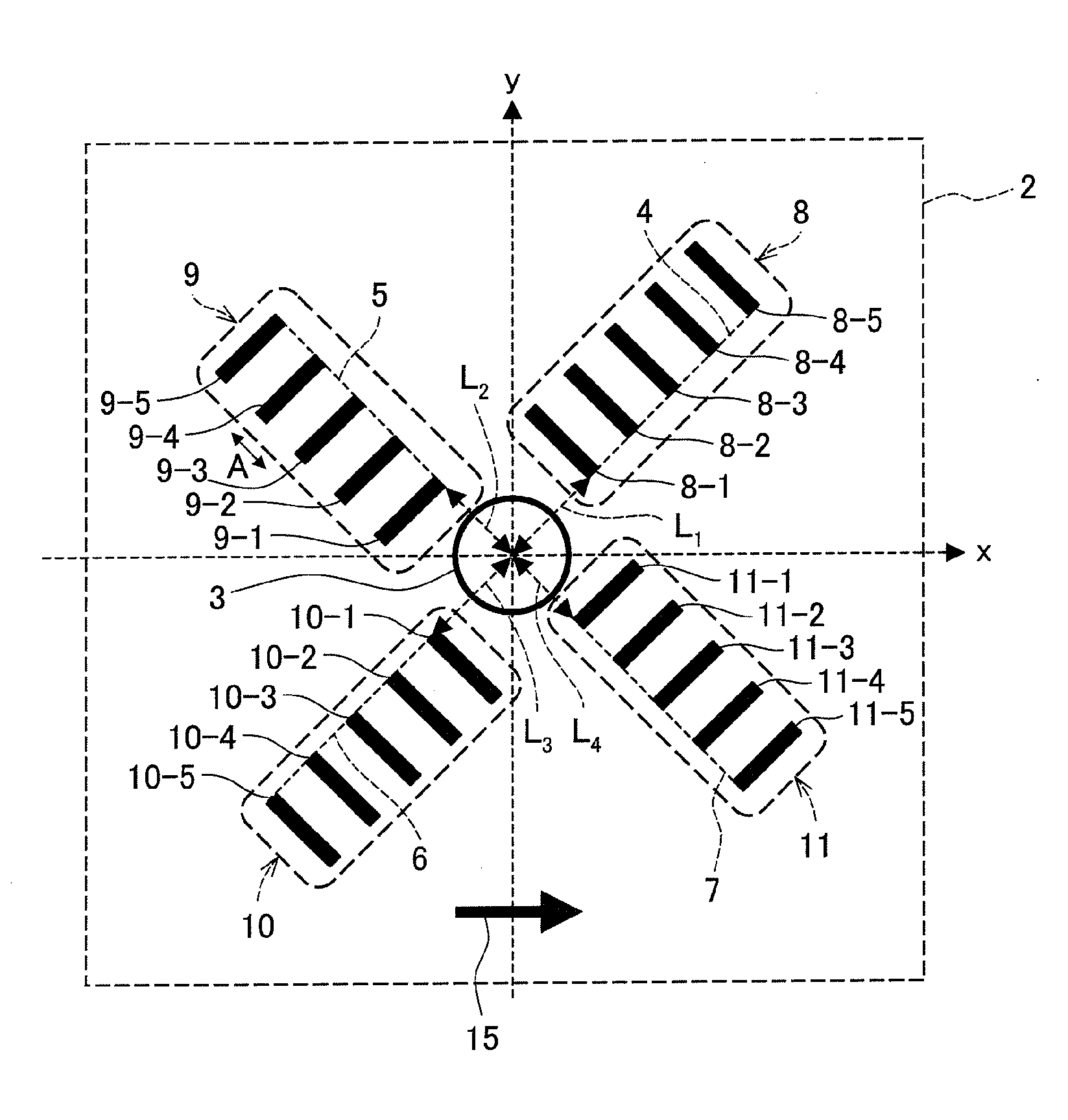
[0061]As illustrated in FIG. 1, an opening 3 serving as a hole is formed on the surface of the metal film 2. Axes 4, 5, 6, and 7 cross each other substantially perpendicularly near the center of the opening 3. For the axis 4, there is provided a periodic groove 8 including grooves 8-1, 8-2, 8-3, 8-4, and 8-5 that are positioned substantially perpendicularly to the axis 4 and are arrayed in the order of closeness to the opening 3.

[0062]Similarly, for the axis 5, there is provided a periodic groove 9 including grooves 9-1, 9-2, 9-3, 9-4, and 9-5 that are positioned substantially perpendicularly to the axis 5 and are arrayed in the order of closeness to the opening 3.

[0063]Similarly, for the axis 6, there is provi...


PUM

PropertyMeasurementUnit
heightaaaaaaaaaa
heightaaaaaaaaaa
widthaaaaaaaaaa

Abstract

An opening (3) is formed on a surface of a metal film (2), a plurality of axes (4, 5, 6, 7) cross each other substantially perpendicularly at the opening (3), a plurality of periodic grooves (8, 9, 10, 11) are provided for respective axes (4, 5, 6, 7), and each of the periodic grooves (8, 9, 10, 11) includes a plurality of grooves (8-n, 9-n, 10-n, and 11-n) substantially perpendicular to the axis for which each periodic groove is provided, and the periodic grooves (8, 9, 10, 11) is positioned point-symmetrically with respect to the opening (3).

Description

TECHNICAL FIELD[0001]The present invention relates to a hybrid storage device for causing information to be stored in an information storage medium. In particular, the present invention relates to a slider for causing magnetic information to be stored in a magnetic storage medium.BACKGROUND ART[0002]A hard disc drive (HDD) has been widely used as an information storage medium. However, recording density of a hard disc drive is increasing more and more, closing to super paramagnetic limit where magnetic information becomes instable.[0003]The super paramagnetic limit is explained below with reference to equation (1).−kmV / kT  (1)[0004]Equation (1) indicates thermal fluctuation constant, and km, V, k, and T indicate magnetic anisotropic energy, recording bit volume, Boltzmann constant, and absolute temperature, respectively. In a conventional medium for magnetic storage (hard disc), volume (V) of recording bit decreases as recording density becomes higher, and consequently the thermal f...

Claims


Application Information

Patent Timeline
Patent Type & Authority Patents(United States)
IPC IPC(8): G11B5/60
CPCB82Y10/00G11B5/102G11B5/314G11B7/1387G11B11/10534G11B11/1058G11B2005/0005G11B2005/0021
Inventor ONO, TOMOKIMIYANISHI, SHINTAROINNAMI, KOUSUKEMURAKAMI, YOSHITERU
Owner SHARP KK
Learn More