
Binary ripple counter sampling with adjustable delays

a delay-adjusting, ripple counter technology, applied in the field of digital signal sampling, can solve the problems of high operating speed, the required resolution of the delay matching between the clock path and the data path increases with increasing operating speed

Active Publication Date: 2011-10-25
TEXAS INSTR INC
View PDF19 Cites 5 Cited by
  • Summary
  • Abstract
  • Description
  • Claims
  • Application Information

AI Technical Summary

Benefits of technology

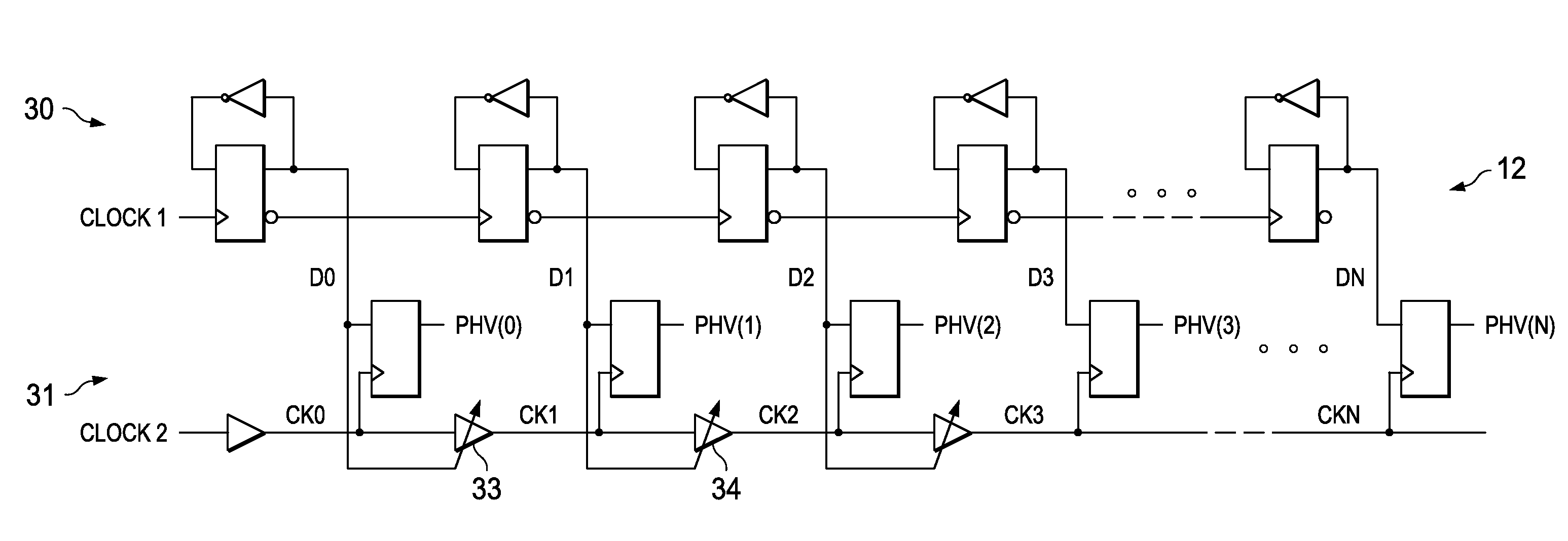
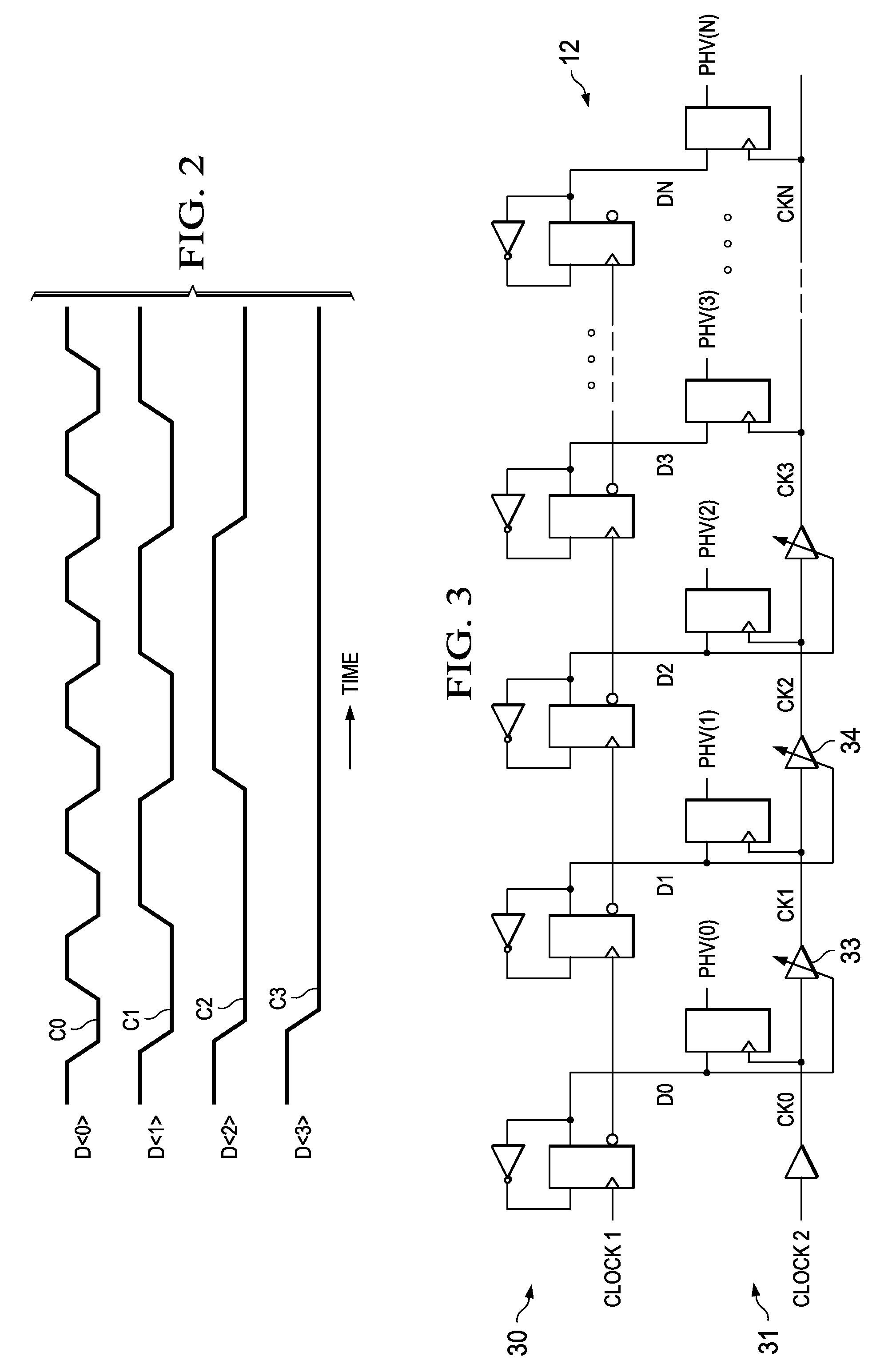
The patent text describes a method for accurately sampling the output bits of a binary ripple counter, even at high operating frequencies. The method involves using a series of adjustable clock delay elements to produce delayed versions of a base sample clock signal that are used to clock the latch stages of a sampler. The delay control inputs of the sampling controller are driven by the output bits of the binary ripple counter, ensuring accurate sampling. This method overcomes the challenges associated with sampling the more significant output bits of the binary ripple counter and with sampling at high operating speeds.

Problems solved by technology

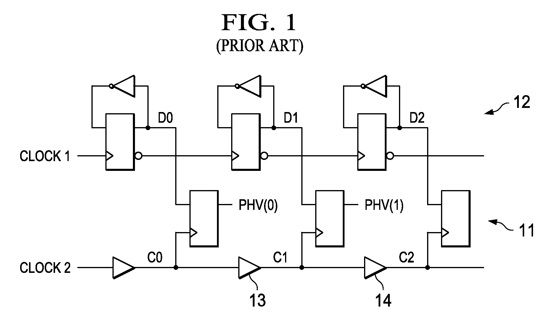
The sampling operations performed by the arrangement of FIG. 1 can be challenging at high operating speeds, due to skew among the output bits D0, D1, D2, etc.
However, the required resolution of the delay matching between the clock path and the data path increases with increases in the operating speed.

Method used


Image

  • Binary ripple counter sampling with adjustable delays
  • Binary ripple counter sampling with adjustable delays
  • Binary ripple counter sampling with adjustable delays

Examples


Embodiment Construction

[0012]According to exemplary embodiments of the invention, the output bits of a binary ripple counter are used to control the sampling of those output bits, thereby ensuring accurate sampling.

[0013]FIG. 3 diagrammatically illustrates an arrangement for sampling the output of a binary ripple counter according to exemplary embodiments of the invention. The arrangement 30 shown in FIG. 3 is generally similar to the arrangement of FIG. 1, and includes the binary ripple counter 12 of FIG. 1. However, the arrangement 30 includes a sampler 31 whose sampling controller employs a series configuration of adjustable clock delay elements 33, 34, etc. that produce respectively delayed versions CK1, CK2, etc. of the base sample clock signal CK0. In some embodiments, CK0 corresponds to C0 of FIG. 1. The clock signals CK0, CK1, CK2, etc. are sample control signals used to clock the respective latch stages of sampler 31 that sample the respective output bits D0, D1, D2, etc. The adjustable clock del...


PUM


Abstract

The output bits of a binary ripple counter are used to control the sampling of those output bits, thereby ensuring accurate sampling. A sampler is provided with adjustable delay elements that permit accurate sampling regardless of: delay mismatch between the sampler and a data path of the counter; the length of the counter; operating speed; or PVT variations.

Description

[0001]This application claims priority to U.S. Provisional Application No. 60 / 945,824, filed on Jun. 22, 2007.FIELD OF THE INVENTION[0002]The invention relates generally to sampling digital signals and, more particularly, to sampling the output bits of a binary ripple counter.BACKGROUND OF THE INVENTION[0003]FIG. 1 diagrammatically illustrates a conventional arrangement including a binary ripple counter 12 coupled to a sampler 11 that samples the output bits D0, D1, D2, etc. from respective count stages of the binary ripple counter. Such an arrangement is useful in many applications. One example is determining the phase of a digitally controlled oscillator (DCO). The structure and operation of the binary ripple counter 12 and the sampler 11 shown in FIG. 1 are known in the art. (See, e.g., US Patent Publication No. 2005 / 0195917, and U.S. Ser. No. 12 / 134,081 entitled “A Low Power All Digital PLL Architecture”, filed Jun. 5, 2008, both of which are incorporated herein by reference.) A...

Claims


Application Information

Patent Timeline
Patent Type & Authority Patents(United States)
IPC IPC(8): H04L7/00
CPCH03K23/58H03K23/662
Inventor ZHUANG, JINGCHENGSTASZEWSKI, ROBERT BOGDAN
Owner TEXAS INSTR INC
Learn More