Bearing device for wheel

a bearing device and wheel technology, applied in the direction of mechanical devices, rigid support of bearing units, transportation and packaging, etc., can solve the problems of deterioration of fuel consumption, interference that the burr presses the seal member, and the end surface of the coupler ring comes into contact with the seal member

Inactive Publication Date: 2011-11-01
JTEKT CORP
View PDF13 Cites 11 Cited by
  • Summary
  • Abstract
  • Description
  • Claims
  • Application Information

AI Technical Summary

Benefits of technology

[0010]A first objective of the present invention is to provide a wheel bearing apparatus which can avoid an interference of a coupler ring with a seal member of a roller bearing.
[0011]A second objective of the present invention is to provide a wheel bearing apparatus which can suppress a deformation of a bearing member arranged within a center hole of an inner shaft caused by a bulge generated in an inner wall of a center hole of an inner shaft on the basis of a caulking of an inner side end portion of the inner shaft.
[0012]A third objective of the present invention is to provide a wheel bearing apparatus which can easily execute a preload control, and can improve a bearing rigidity.
[0013]In order to achieve the first objective mentioned above, in accordance with one aspect of the present invention, there is provided a wheel bearing apparatus provided with a roller bearing, an inner shaft, a coupler ring, a caulked portion, and an avoiding structure. The roller bearing has an outer ring, an inner ring, a rolling element, and a seal member. The inner shaft has a center hole allowing insertion of a drive shaft. The inner ring of the roller bearing is installed to an outer circumferential surface of the inner shaft. The coupler ring is attached to an end portion of the inner shaft. The caulked portion is provided in the end portion of the inner shaft for fixing the coupler ring and the roller bearing to the inner shaft so as to be immobile in an axial direction of the inner shaft. The avoiding structure is provided for avoiding an interference of the coupler ring with a seal member of the roller bearing.

Problems solved by technology

Accordingly, there is a risk that the end surface of the coupler ring comes into contact with the seal member provided in the roller bearing.
Accordingly, in the case that the end surface of the outer circumferential spline of the coupler ring comes into contact with the seal member, such an interference that the burr presses the seal member may be generated.
As a result, a rotation of the drive shaft is obstructed, thereby causing a deterioration of the fuel consumption and a deterioration of the durability of the needle bearing and the drive shaft.
Further, in the case of the shaft end caulking, it is not easy to accurately apply a preload having a desired magnitude to the bearing.
In other words, it becomes complicated to control the preload for accurately applying the preload having the desired magnitude to the bearing and a lot of manufacturing processes are required.

Method used


Image

  • Bearing device for wheel
  • Bearing device for wheel
  • Bearing device for wheel

Examples


fourth embodiment

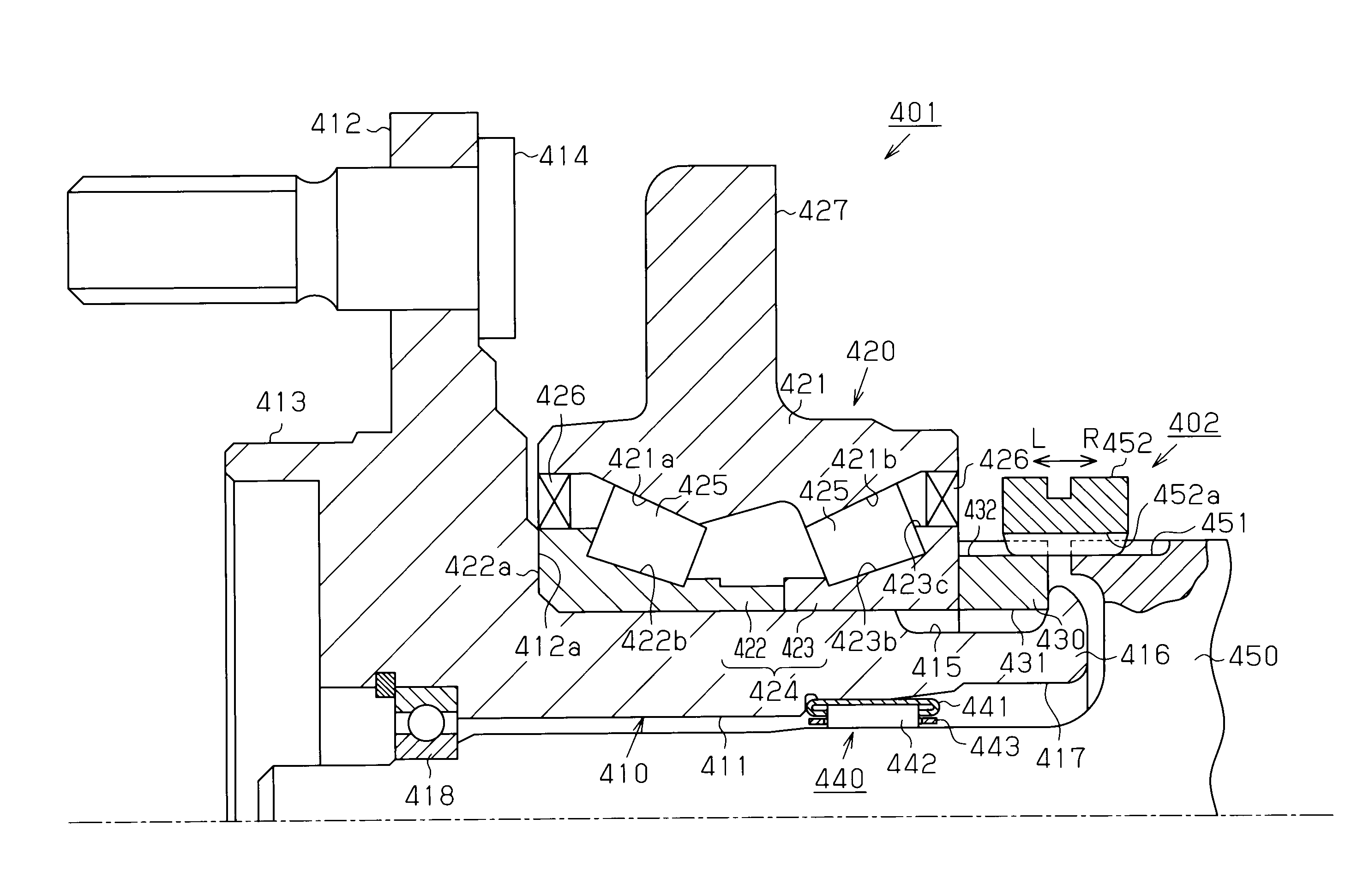
[0055]Next, a description will be given of a wheel bearing apparatus in accordance with the present invention with reference to FIGS. 4 and 5. FIG. 4 is a longitudinal cross-sectional view of a wheel bearing apparatus 401. The wheel bearing apparatus 401 is provided with an inner shaft 410, a roller bearing 420, a coupler ring 430, and a needle bearing 440.

[0056]The inner shaft 410 has a shaft portion 411, an annular flange portion 412 formed in an outer side end portion of the shaft portion 411 in such a manner as to extend radially outward, and a cylindrical socket portion 413 protruding so as to protrude further to a vehicle outer side than the flange portion 412. A wheel (not shown) is fastened to the flange portion 412 by a bolt 414. A roller bearing 420 for rotatably supporting the inner shaft 410 with respect to a suspension apparatus of a vehicle body (not shown) is installed to an outer circumferential surface of a center portion in an axial direction of the shaft portion 4...

fifth embodiment

[0083]Next, a description will be given of a wheel bearing apparatus in accordance with the present invention with reference to FIG. 9.

[0084]As shown in FIG. 9, a disc-shaped or cross-shaped flange portion 501a is provided in an outer circumferential surface of an end portion in a vehicle outer side (a left side in FIG. 9) of a hub shaft 501 in such a manner as to extend radially outward. The wheel (not shown) is fastened to the flange portion 501a via a bolt 500b. Further, an external thread portion 511a into which a coupler ring 503 mentioned below is screwed is formed in an outer circumferential surface of an end portion 501e in a vehicle inner side (a right side in FIG. 9) of the hub shaft 501. FIG. 9 shows a wheel bearing apparatus arranged in a left side of a vehicle such as a motor vehicle or the like, and in the drawing, the external thread portion 511a is formed as a right-handed screw in such a manner that the coupler ring 503 is fastened into the hub shaft 501 in accordan...


PUM


Abstract

A wheel bearing apparatus includes a roller bearing, an inner shaft having an outer circumferential surface to which an inner ring of the roller bearing is installed, a coupler ring attached to an end portion of the inner shaft, and a caulked portion provided in an end portion of the inner shaft so as to fix the coupler ring and the roller bearing to the inner shaft so as to be immovable in an axial direction of the inner shaft. An outer diameter of the coupler ring is set smaller than a diameter of a shoulder portion of the inner ring. Alternatively, a protruding portion is provided in any one of opposing end surfaces of the coupler ring and the inner ring, whereby the coupler ring is arranged away from a seal member. Accordingly, it is possible to avoid an interference of the coupler ring with the seal member.

Description

FIELD OF THE INVENTION[0001]The present invention relates to a wheel bearing apparatus which is mainly used in a vehicle such as a motor vehicle or the like.DISCUSSION OF THE BACKGROUND[0002]As a wheel bearing apparatus for a part-time 4WD vehicle which can be switched between a two-wheel drive (2WD) mode and a four-wheel drive (4WD) mode, there has been known a structure which can selectively couple a drive shaft (an axle) connected to an engine to a wheel and cancel the coupling, that is, can selectively allow and shut off a transmission of a driving force from the drive shaft to the wheel (refer, for example, to Patent Documents 1 and 2).[0003]In the wheel bearing apparatus mentioned above, a roller bearing for rotatably supporting an inner shaft (a hub shaft) with respect to a suspension apparatus is installed to an outer circumference of the inner shaft to which the wheel is attached. A center of the inner shaft is provided with a center hole to which a drive shaft is inserted....

Claims


Application Information

Patent Timeline
Patent Type & Authority Patents(United States)
IPC IPC(8): F16C13/00B60B27/00
CPCB60B27/001F16C19/386F16C35/063F16C2326/02B60B35/14B60B35/18F16C19/38
Inventor KAMIKAWA, TSUYOSHITAKADA, YOSHITODEGUCHI, MASARUADACHI, KENTSUZAKI, YOUICHIYAMAMOTO, SEIJIYU, CHANGXINTAKIMOTO, MASAOISHIKAWA, TETSUYANAGATA, SYUUJI
Owner JTEKT CORP
Why Eureka
Try Eureka