Wall plate bracket

a technology for wall plates and brackets, which is applied in the direction of machine supports, electrical apparatus casings/cabinets/drawers, coupling device connections, etc., can solve the problems of obstructing the interior of the support housing, and limiting the clearance between the support housing and the rear surface, etc., to achieve the effect of compactness

Active Publication Date: 2011-11-01
THOMAS & BETTS INT INC
View PDF76 Cites 26 Cited by
  • Summary
  • Abstract
  • Description
  • Claims
  • Application Information

AI Technical Summary

Benefits of technology

[0007]The wall plate may have a rib which is connected to the rear surface of the wall plate. The rib is located relative to the interior opening such that the rib is located between the support housing and rear surface. The rib which is connected to the rear surface covers a portion of the clearance or gap between the support housing and rear surface which reduces the clearance. Limiting the clearance between the support housing and rear surface obstructs access to the interior of the support housing where the high voltage outlet is located. Consequently, reducing the clearance facilitates compliance with the building and electrical codes which limit the size of the clearance.
[0009]The wall plate bracket of the present invention also provides for the connection of the support housing to a planar high voltage plate, and the support of a low voltage connector on a planar low voltage plate. The high and low voltage plates are connected to a faceplate such that the high and low voltage plates extend rearwardly relative to the faceplate. Access to the high and low voltage plates is provided through an interior opening of the faceplate. The low voltage plate intersects the high voltage plate which simplifies and makes more compact the configuration of the high and low voltage plates.

Problems solved by technology

Limiting the clearance between the support housing and rear surface obstructs access to the interior of the support housing where the high voltage outlet is located.
This limits the clearance between the support housing and rear surface.

Method used


Image

  • Wall plate bracket
  • Wall plate bracket
  • Wall plate bracket

Examples


Embodiment Construction

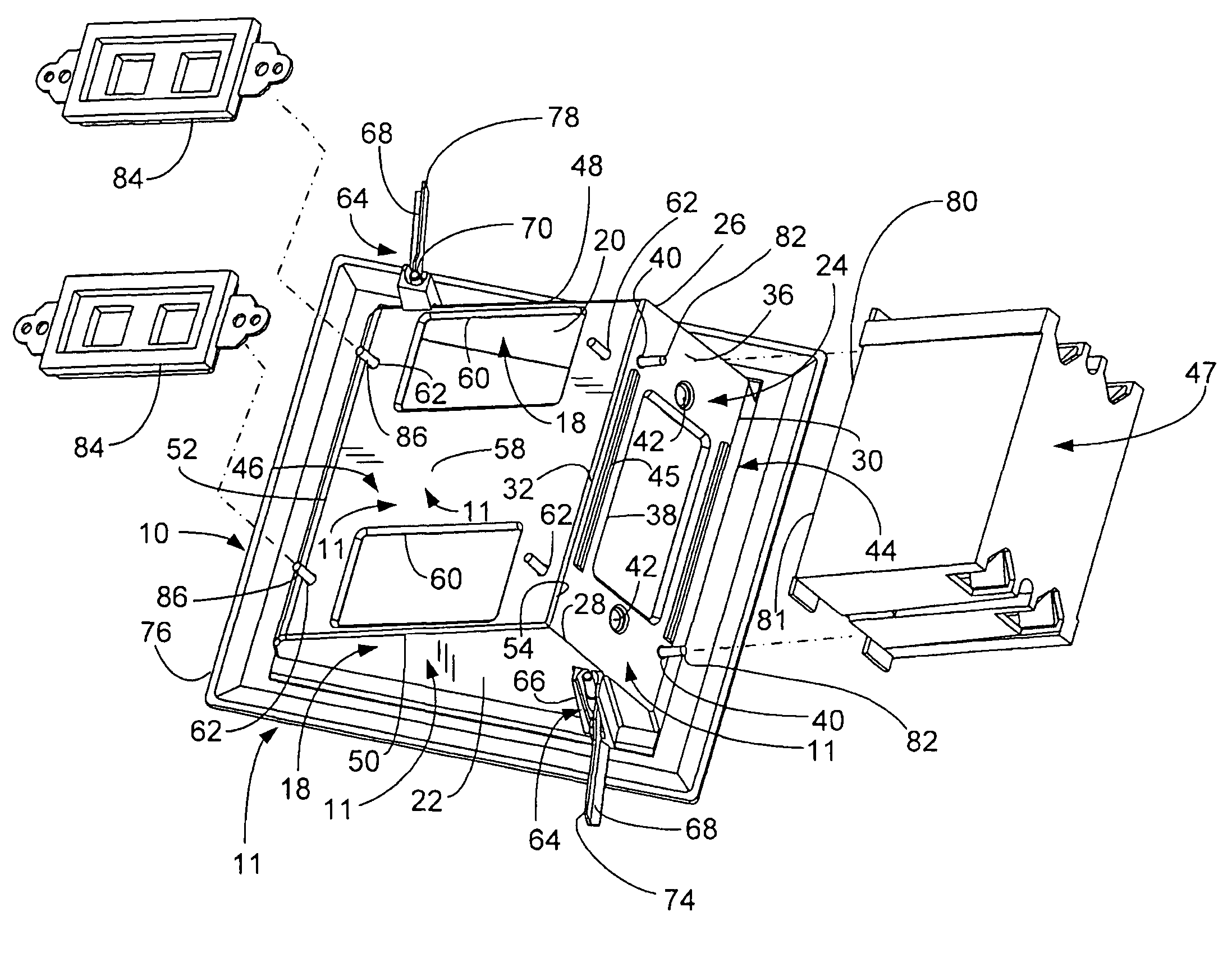
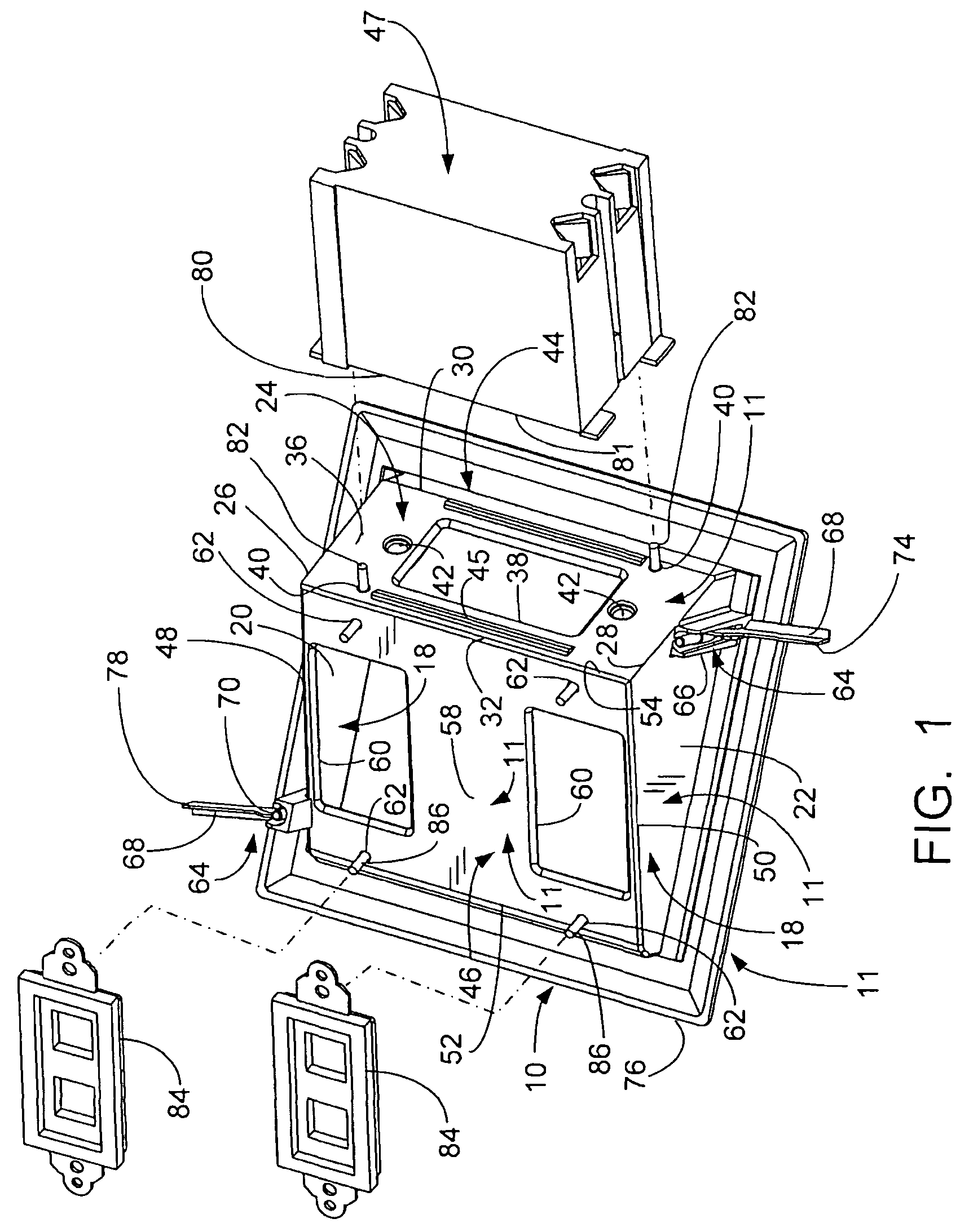
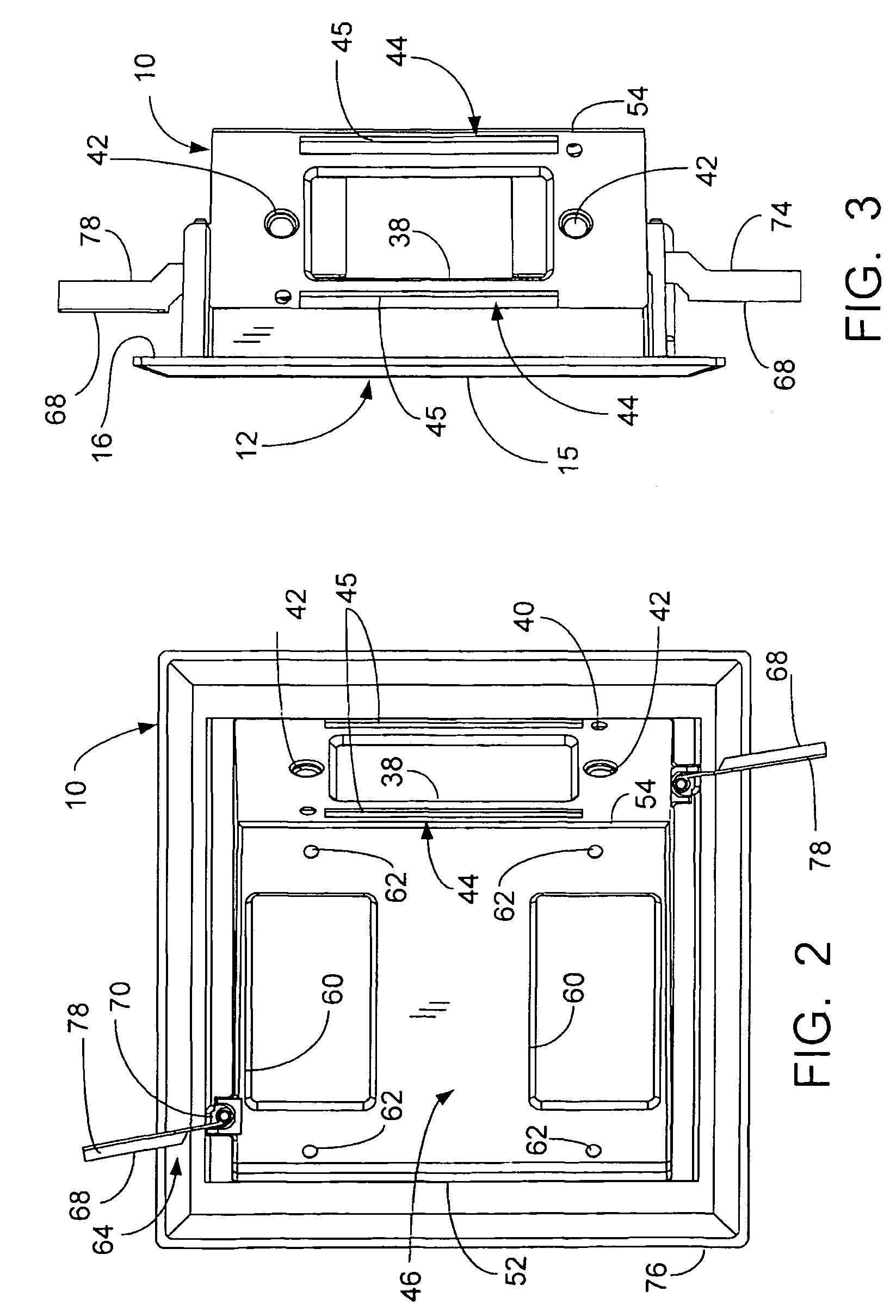
[0027]Referring to the drawings and more particularly to FIGS. 1 to 7, a wall plate bracket 10 is shown for mounting to a wall structure, such as the vertical wall board of an interior wall of a building structure.

[0028]The wall plate bracket 10 includes a wall plate 11. The wall plate 11 includes a faceplate 12 which has an opening 14. The faceplate 12 has front and rear surfaces 15, 16.

[0029]The wall plate 11 includes a flange structure 18 which is secured to the rear surface 16. The flange structure 18 includes opposing flanges 20, 22 which have a perpendicular orientation relative to the faceplate 12. The flanges 20, 22 are located relative to the faceplate 12 such that the opening 14 is between the flanges.

[0030]The wall plate 11 includes a planar high voltage plate 24 which has end edges 26, 28 and side edges 30, 32. The high voltage plate 24 is connected to the faceplate 12 by the side edge 30 being fixed thereto. The faceplate 12 is connected to the flange 20 by the end edge...


PUM


Abstract

The wall plate bracket is for a high voltage outlet, and includes a wall plate having front and rear surfaces. The wall plate has an interior opening. A support housing has an inner surface and an interior region bounded by the inner surface. The support housing is connected to the rear surface such that the interior opening provides access to the interior region. The support housing is configured for support of the high voltage outlet within the interior region. A clamp is connected to the wall plate for securing the wall plate to a wall structure. The rear surface of the wall plate may have a rib to limit the clearance between the support housing and rear surface. Alternatively, the clearance may be limited by a recess in the rear surface in which a mounting tab of the support housing is located.

Description

BACKGROUND OF THE INVENTION[0001]The present invention relates generally to a wall plate bracket for mounting one or more high voltage outlets and low voltage connectors on wall structures, and more particularly, to such a bracket in which outlets and connectors are recessed from the wall structure.[0002]The high voltage outlets have receptacles into which are inserted the prongs of an electrical plug for supplying electrical power to a conductor which is connected to the plug. High voltage outlets are also known as electrical power outlets. The high voltage outlet includes a support housing, which may be a box, within which the receptacles for the prongs of the electrical plug are supported. The support housing is secured to a stud in the wall structure such that the receptacles of the high voltage outlet are accessible through an opening in the wall structure from the front thereof. A wall plate is secured to the front of the support housing such that the wall surface of the wall ...

Claims


Application Information

Patent Timeline
Patent Type & Authority Patents(United States)
IPC IPC(8): H02G3/08H01H9/02
CPCH02G3/14H02G3/18Y10S248/906
Inventor DINH, CONG THANH
Owner THOMAS & BETTS INT INC
Why Eureka
Try Eureka