Solar collector with end modifications

a solar collector and end modification technology, applied in the field of solar energy collection systems, can solve the problems of increasing cost and system complexity, not one has achieved significant commercial success, and limited to utilizing less than all of the total available ligh

Active Publication Date: 2011-11-01
SKYLINE SOLAR INC +1
View PDF56 Cites 38 Cited by
  • Summary
  • Abstract
  • Description
  • Claims
  • Application Information

AI Technical Summary

Problems solved by technology

Although many CPV designs have been developed from the very beginning of the commercial PV industry in the 1960's, not one has achieved significant commercial success.
Although CPV designs use less active cell material, they typically require additional structure such as minors, lenses and heat sinks, and are fundamentally limited to utilizing less then all of the total available light.
These factors increase cost and system complexity and reduce the optical-to-electrical efficiency over non-concentrating PV systems.

Method used


Image

  • Solar collector with end modifications
  • Solar collector with end modifications
  • Solar collector with end modifications

Examples


example solar

[0026 Collector

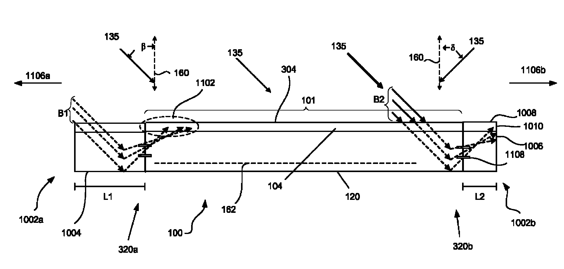
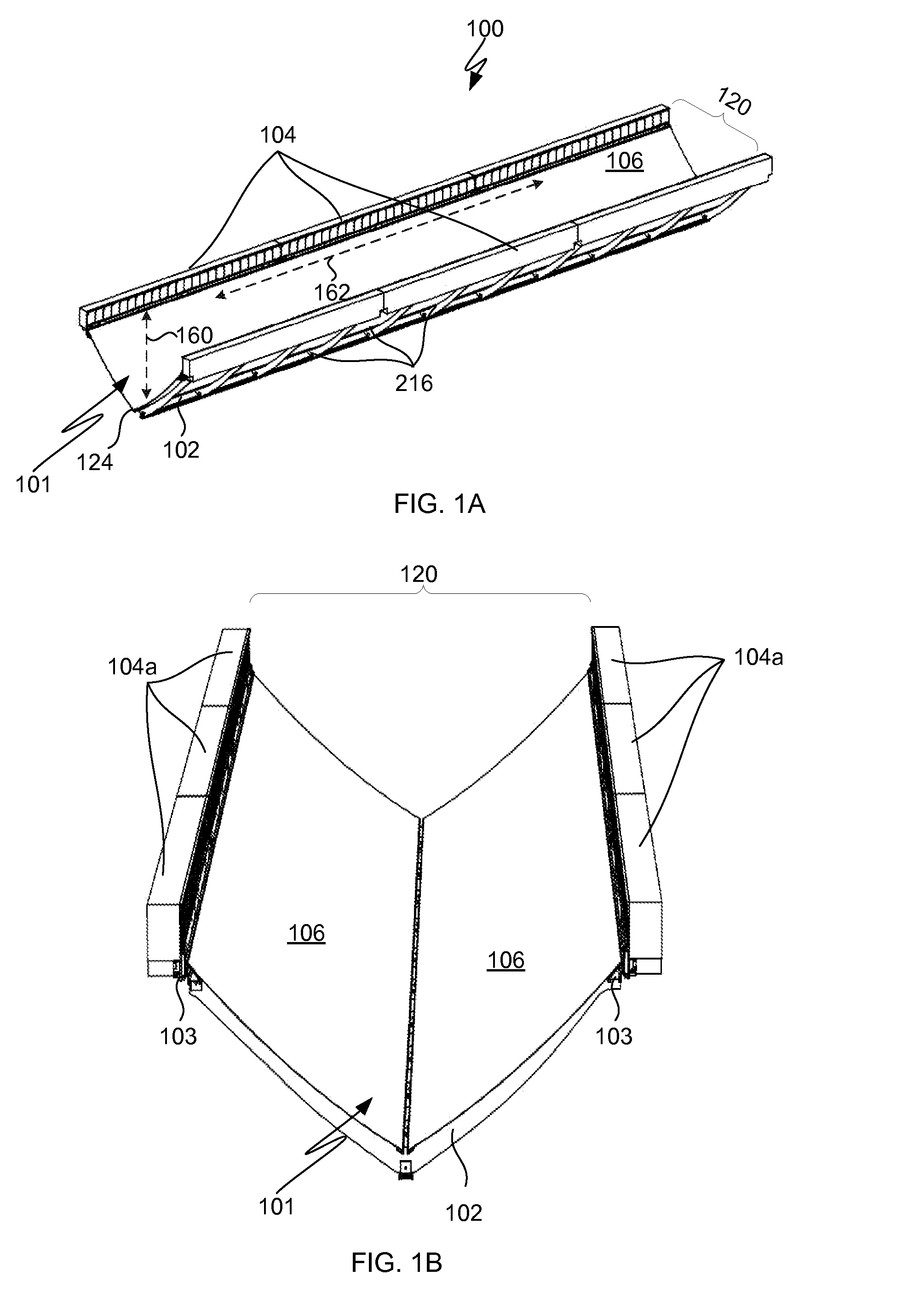
[0027]Although an example one-dimensional tracking solar energy collector is described, this is not intended to be limiting as any type and style of trough collector may be used. By way of example, any collector described in patent application Ser. No. 12 / 100,726, entitled “Dual Trough Concentrating Solar Photovoltaic Module,” filed Apr. 10, 2008, which is hereby incorporated by reference in its entirety for all purposes, may be used in connection with any of the embodiments, features and components described herein. FIGS. 1A-1D illustrate an embodiment of a single trough solar energy concentrator or collector. FIG. 1A is a perspective view of the single trough solar energy collector and FIG. 1B is a top perspective view of the single trough solar energy collector. The collector 100 has an optical aperture 101 designed to admit incident sunlight onto reflector panels 106. A support structure 102 is arranged to support reflector panels 106 and reflector panels 106 are ...


PUM

PropertyMeasurementUnit
angle of incidenceaaaaaaaaaa
widthaaaaaaaaaa

Abstract

In one embodiment, a concentrating solar energy collector, which tracks movements of the sun along one axis has a reflective trough, at least one solar receiver mounted above the reflective trough and configured so that incident sunlight striking the reflective trough is directed toward the at least one solar receiver, and a reflector extender coupled to a first end of the reflective trough and configured to capture and direct incident sunlight towards the at least one solar receiver. In another embodiment, one or more extended end reflectors is attached with a reflective trough of a solar energy collector.

Description

CROSS-REFERENCE TO RELATED APPLICATIONS[0001]This application claims priority to U.S. Provisional Patent Application No. 61 / 144,057, entitled “Solar Collector with End Modifications,” filed Jan. 12, 2009, which is hereby incorporated by reference in its entirety for all purposes.FIELD OF THE INVENTION[0002]The present disclosure relates generally to solar energy collecting systems, and more particularly to concentrating solar energy collecting systems.BACKGROUND OF THE INVENTION[0003]The highest cost components of a solar photovoltaic (PV) system are the solar cells that convert sunlight to electricity by the photoelectric effect. To use these cells more effectively, concentrating photovoltaic (CPV) systems focus sunlight from a larger aperture onto a smaller cell area. Although many CPV designs have been developed from the very beginning of the commercial PV industry in the 1960's, not one has achieved significant commercial success. Although CPV designs use less active cell materi...

Claims


Application Information

Patent Timeline
Patent Type & Authority Patents(United States)
IPC IPC(8): H01L31/052F24S50/20F24S23/70
CPCF24J2/07F24J2/10F24J2/14F24J2/541H01L31/0547Y10T29/49002Y02E10/45Y02E10/47Y02E10/52Y02E10/41F24S20/20F24S23/70F24S23/74F24S30/425Y02E10/40
Inventor JOHNSON, ERIC C.BILODEAU, JAMES L.WELLS, JASON R.NIGHTINGALE, JOHN L.FINOT, MARC A.
Owner SKYLINE SOLAR INC
Why Eureka
Try Eureka