Solar energy collector

a solar energy collector and collector technology, applied in the field of solar energy, can solve the problems of complex mechanical arrangement and energy collection system

Inactive Publication Date: 2012-04-24
MARTIN LOPEZ FERNANDO RAMON
View PDF19 Cites 7 Cited by
  • Summary
  • Abstract
  • Description
  • Claims
  • Application Information

AI Technical Summary

Problems solved by technology

These prior art solar energy collection systems are disadvantageous in that they involve complex mechanical arrangements for tracking the sun's position.

Method used


Image

  • Solar energy collector
  • Solar energy collector
  • Solar energy collector

Examples


Embodiment Construction

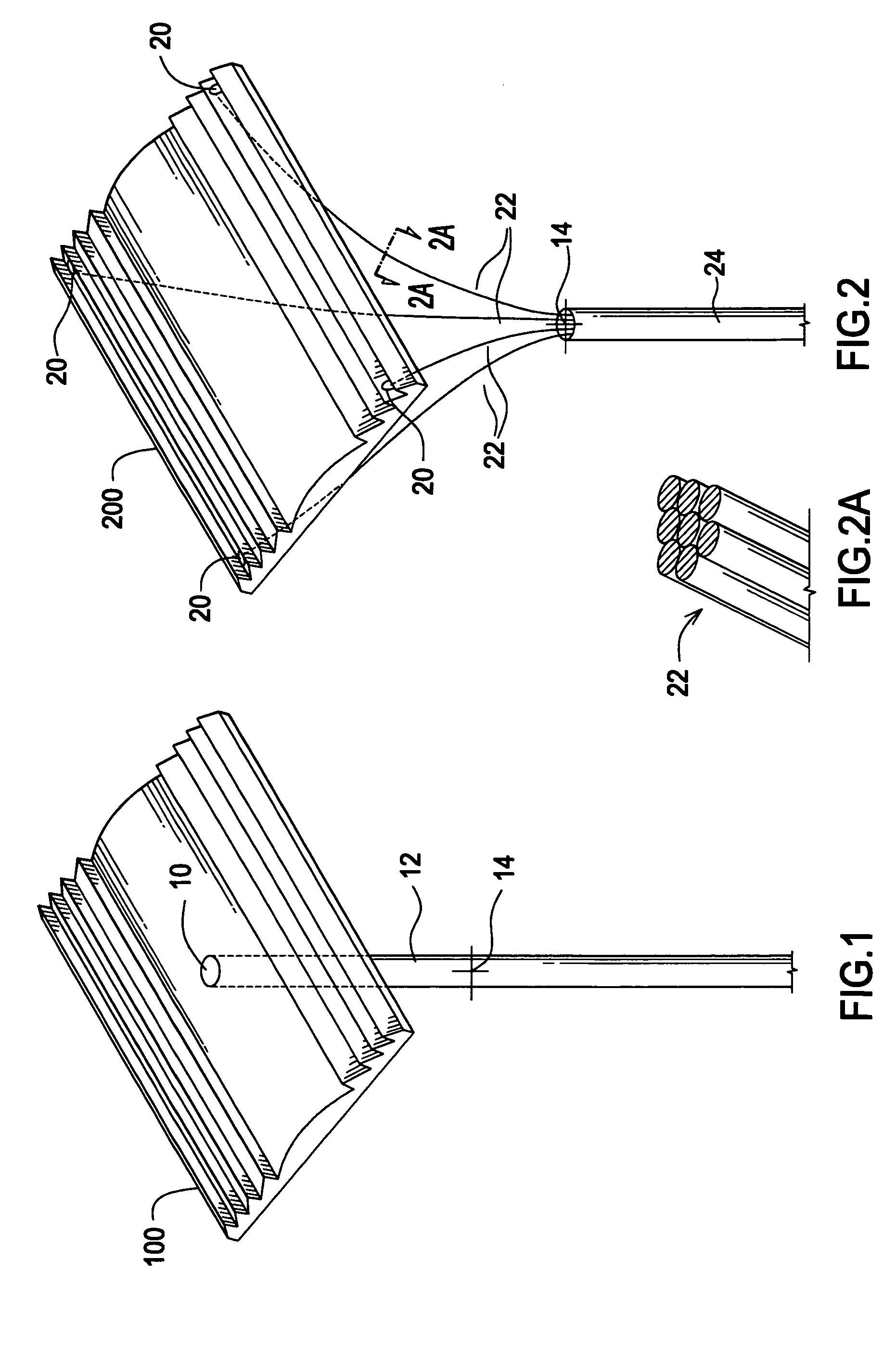
[0020]Referring now to FIG. 1, there is shown a Fresnel lens 100 having a central circular opening 10 therein. Fresnel lens 100 may comprise, for example, an inexpensive Fresnel lens having a focal length of approximately one inch and commercially available from such companies as 3Dlens.com. These lenses are approximately 52 mm by 82 mm (2 inches by 3.2 inches) in length and width and are approximately 0.016 inches in thickness. Circular opening 10 may be simply drilled in Fresnel lens 100 to accommodate a fiber optic cable 12 that is inserted through Fresnel lens 100 from the underside thereof. Fiber optic cable 12 may be held in place by means of any of a number of commercially-available fasteners, not illustrated, such as o-rings or cable ties, for example, secured over fiber optic cable 12 on either side of Fresnel lens 100. Fiber optic cable 12 receives sunlight at a focal point 14 that is approximately one inch below Fresnel lens 100. Fiber optic cable 12 may be of the type ma...


PUM


Abstract

A multiplicity of Fresnel lenses are attached to tubular branches of a tree-like support structure. Fiber optic bundles are connected to the Fresnel lenses and routed inside the tubular branches and collected as a larger fiber optic bundle inside a main trunk structure to which each of the branches is connected. The larger fiber optic bundle may be connected to a remotely located power generating plant or other processing facility via a fiber optic transmission network. A domed solar energy collector includes an outer dome and one or more inner domes concentrically nested therewith, one or more Fresnel lenses being positioned on the hemispherical surface of each of the outer and inner domes. Each of the inner domes is sized and positioned such that its hemispherical surface lies on the focal point of the next larger dome to thereby multiply the solar energy focused through each of the domes to a collection area within the innermost dome. Solar energy is collected by either a fiber optic network or a photovoltaic panel positioned in the collection area.

Description

BACKGROUND AND SUMMARY OF THE INVENTION[0001]This invention relates generally to solar energy and, more particularly, to the collection of solar energy through the use of Fresnel lenses in various configurations.[0002]Numerous devices for harnessing the sun's energy are well known in the prior art. U.S. Pat. No. 4,723,826 is directed to a conventional fiber optic solar energy collector employing a matrix of lenses mounted in a fixed position. One or two plates placed in the focal plane of the lenses are moved to track the sun's position during the daylight hours. U.S. Pat. No. 7,295,372 is directed to an apparatus for collecting and transmitting sunlight into a space. U.S. Patent Application Publication No. US 2006 / 0165358 is directed to a fiber optic connection system including compact bundles of light guides with sections having a reduced interstitial area. U.S. Patent Application Publication No. 2007 / 0137640 is directed to a solar energy collecting system that tracks the sun and ...

Claims


Application Information

Patent Timeline
Patent Type & Authority Patents(United States)
IPC IPC(8): G02B6/32F24J2/10F24J2/08H02N6/00H01L31/042F24S23/00F24S23/30F24S23/70
CPCF24J2/067F24J2/085F24J2/5203F24J2/523H01L31/0547H01L31/0543Y02E10/43Y02E10/47Y02E10/52F24J2002/0416F24S23/12F24S23/31F24S25/10F24S25/30F24S2020/186
Inventor MARTIN-LOPEZ, FERNANDO RAMON
Owner MARTIN LOPEZ FERNANDO RAMON
Why Eureka
Try Eureka