
Calibration System For Solar Collector Installation

a solar collector and calibration system technology, applied in the field of calibration, can solve the problems of high cost associated with site preparation and fabrication of such a foundation, affecting the economic viability of installing large-area structures, and affecting the economic viability of large-area installations

Inactive Publication Date: 2011-01-27
CEWA TECH
View PDF21 Cites 7 Cited by
  • Summary
  • Abstract
  • Description
  • Claims
  • Application Information

AI Technical Summary

Benefits of technology

[0011]It is an advantage of the arrangement of the present invention that the calibration tool is only required upon initial installation of a solar collector. Once the calibration is performed, the tool may be removed and is ready for use with another collector installation.
[0012]Moreover, the use of a calibration tool to perfect the alignment between the sun and the collector has been found to reduce the accuracy required in preparing the installation site, constructing the individual components of the system and building the system in the field. These reductions yield a significant cost savings over prior art arrangements that relied on precise alignment upon installation.

Problems solved by technology

While numerous tracking systems have been designed and implemented, problems remain with site preparation, “stack-up” tolerances as a result of the solar collector fabrication and assembly, as well as with the installation of the collector itself at the site.
The high costs associated with site preparation and fabrication of such a foundation impacts the economic viability of installing large-area solar collector fields (that is, an installation of a large number of separate collectors which are then operated as a “system”).

Method used


Image

  • Calibration System For Solar Collector Installation
  • Calibration System For Solar Collector Installation
  • Calibration System For Solar Collector Installation

Examples


Embodiment Construction

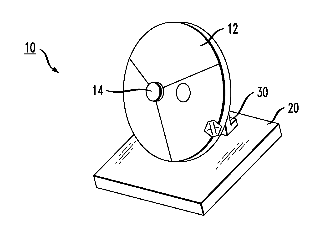
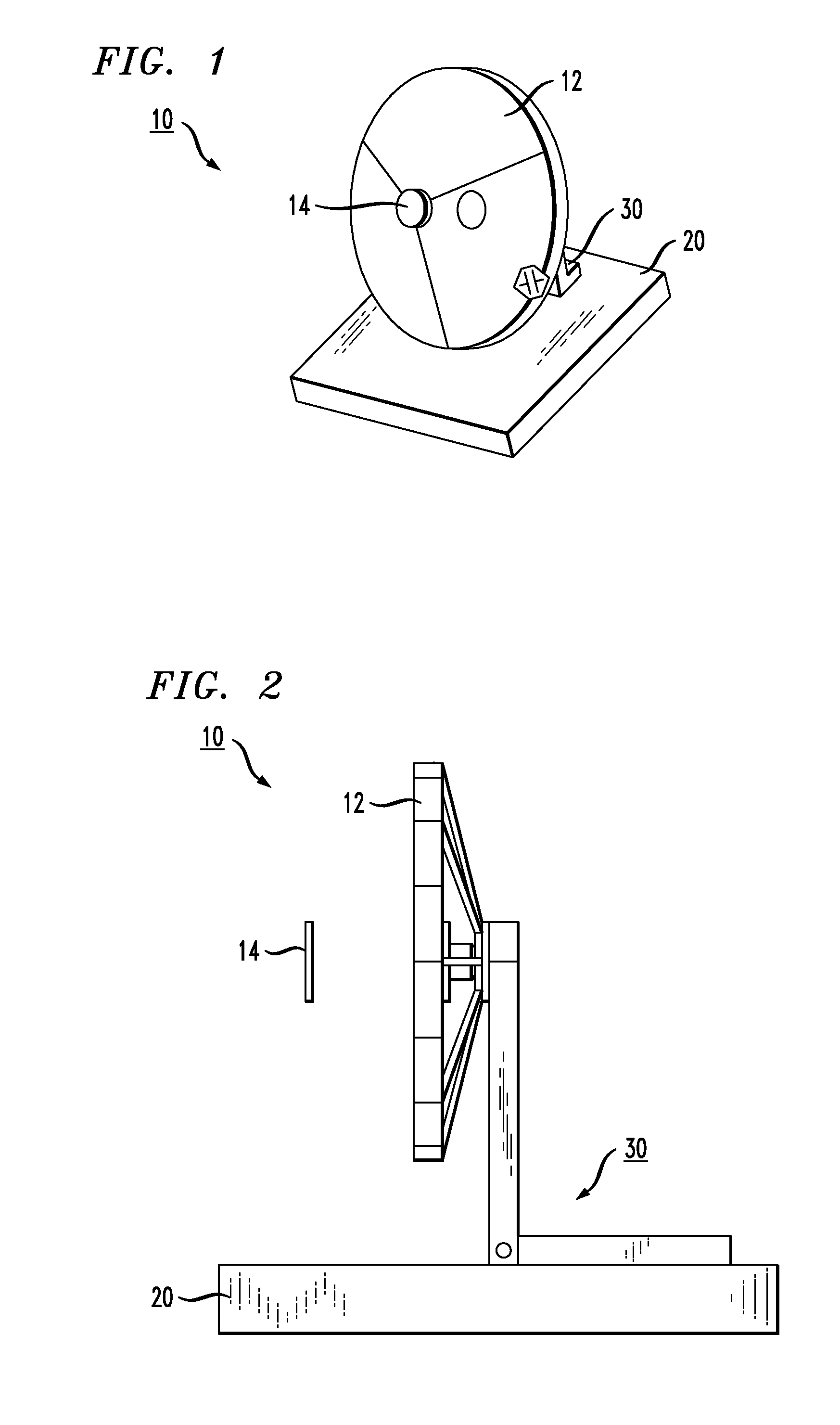
[0019]FIG. 1 is a simple illustration of an exemplary solar collector 10 that can be calibrated with the system of the present invention to provide a tracking program that overcomes imperfections that may exist in the system components, installation site preparation and / or on-site construction of the solar collector itself. In this particular example, solar collector 10 includes a concentrating reflector 12 for re-directing impinging solar radiation onto a receiver 14 (or a secondary reflector positioned at that location). At an installation site, collector 10 may be attached to, for example, a concrete pad 20, or similar support structure. A mounting structure 30 is used to attach collector 10 to pad 20. Although not explicitly shown in this view, structure 30 also includes servomechanisms used to move collector 10 so as to track the sun's movement during the course of the day. A side view of the arrangement of FIG. 1 is shown in FIG. 2, which illustrates a particular configuration...


PUM


Abstract

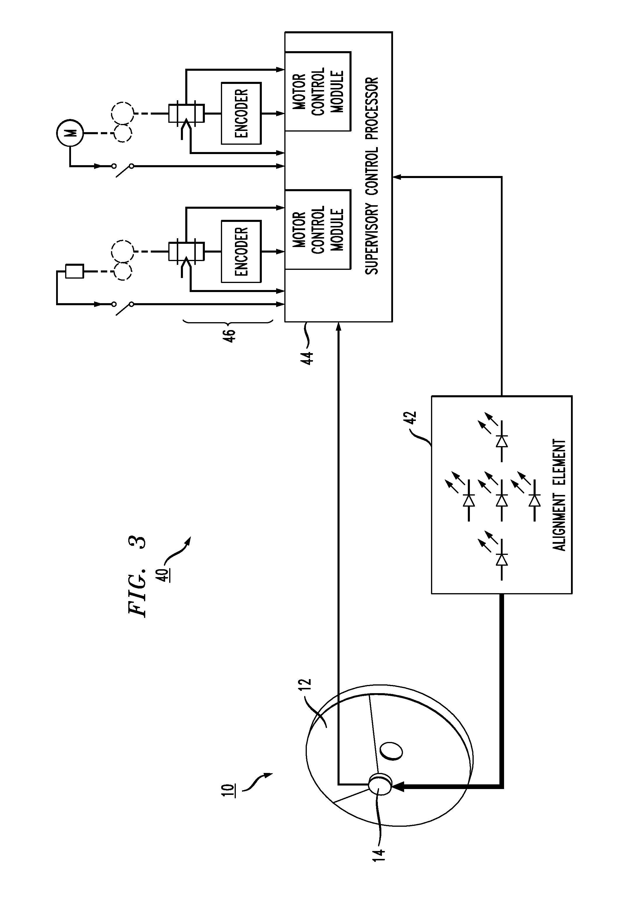
A solar concentrator calibration tool that compensates for inconsistencies in the fabrication, assembly and installation of a solar collector system, permitting the solar collector to perform optimally. The calibration tool provides feedback information to a supervisory control processor, allowing the processor to compare the expected position of the sun to the “actual” position found by the calibration tool. The processor then generates a calibration signal, thereafter used by the collector's movement control mechanism, to compensate the tracking of the solar collector to accurately follow the movement of the sun, unconstrained by the effects of the construction inconsistencies.

Description

CROSS-REFERENCE TO RELATED APPLICATION[0001]The application claims the benefit of U.S. Provisional Application No. 61 / 228,440, filed Jul. 24, 2009 and herein incorporated by reference.TECHNICAL FIELD[0002]The present invention relates to the installation of a solar collector and, more particularly, to a system for providing alignment between the sun and the collector, regardless of the physical characteristics of the solar collector support system.BACKGROUND OF THE INVENTION[0003]In the increasingly important field of renewable energy production, solar power is a highly promising technology. In some cases, this technology employs solar cells, also known as photovoltaic (PV) cells, to convert solar radiation into direct current electricity. Solar cells may be arranged into arrays of flat panels, in which sunlight directly impinges upon large surface areas of solar cells. Or, solar cells may be used in photovoltaic concentrators, in which mirrors and lenses reflect and focus solar ene...

Claims


Application Information

Patent Timeline
IPC IPC(8): G01J1/20F24S23/70F24S23/71F24S23/79F24S50/20
CPCF24J2/1047H01L31/0547F24J2/12F24J2/18F24J2002/1085F24J2002/385Y02B10/20Y02E10/42Y02E10/52F24J2/38Y02E10/47H01L31/058H02S40/00H01L31/056H01L31/052H02S40/44F24J2/1057F24S23/71F24S23/79F24S23/80F24S23/82F24S50/20F24S2023/874F24S2050/25Y02E10/60G01D5/3473H01L31/02024H02S20/32Y02E10/40
Inventor FANGMAN, MICHAEL E.
Owner CEWA TECH
Learn More