MRI RF encoding using multiple transmit coils

a technology of rf transmit coil and mri, which is applied in the field of magnetic resonance system, can solve problems such as rf encoding with respect to image quality

Inactive Publication Date: 2011-11-01
KONINK PHILIPS ELECTRONICS NV
View PDF9 Cites 3 Cited by
  • Summary
  • Abstract
  • Description
  • Claims
  • Application Information

AI Technical Summary

Problems solved by technology

This assumption is usually not fulfilled in practice, leading to limitations of RF encoding with respect to image quality.

Method used


Image

  • MRI RF encoding using multiple transmit coils
  • MRI RF encoding using multiple transmit coils
  • MRI RF encoding using multiple transmit coils

Examples


Embodiment Construction

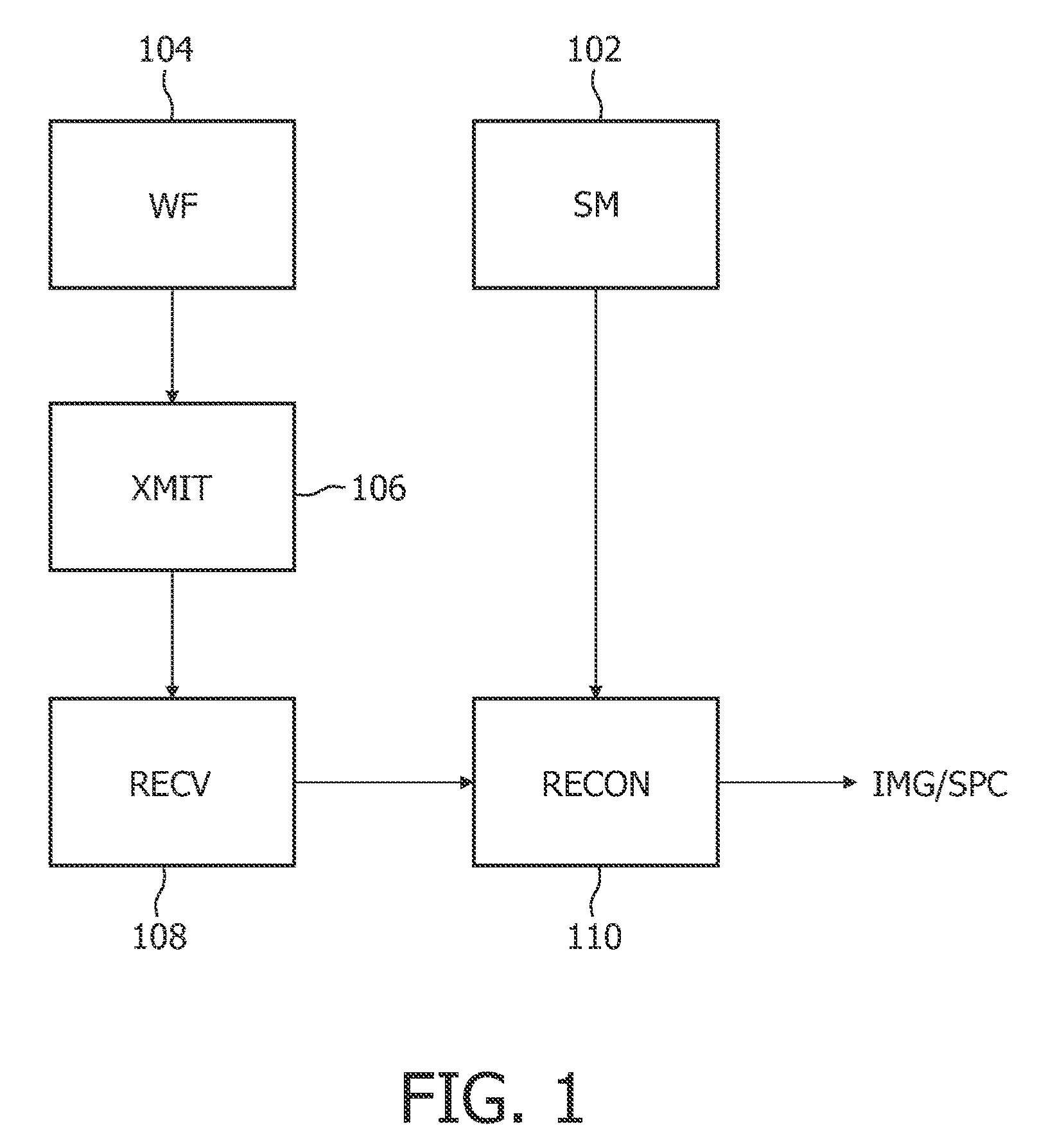
[0016]FIG. 1 diagrammatically shows an embodiment of the method of operating an MR system as disclosed herein. In a mapping step (SM) 102, a map of the transmit sensitivities values of a plurality of RF transmit coils is obtained. A set of weighting factors for individual RF transmit coils, calculated based on transmit sensitivities of individual coils as well as on a desired B1 gradient value, is obtained in a weighting step (WF) 104. RF excitation is applied during excitation to a subject in an excitation step (XMIT) 106, and MR signals generated from the subject in response to the RF excitation are received in a receiving step (RECV) 108. A single complex data point is acquired for every application of the B1 gradient. The received MR signals are processed in a processing step (RECON) 110 to yield an MR image or an MR spectrum IMG / SPC.

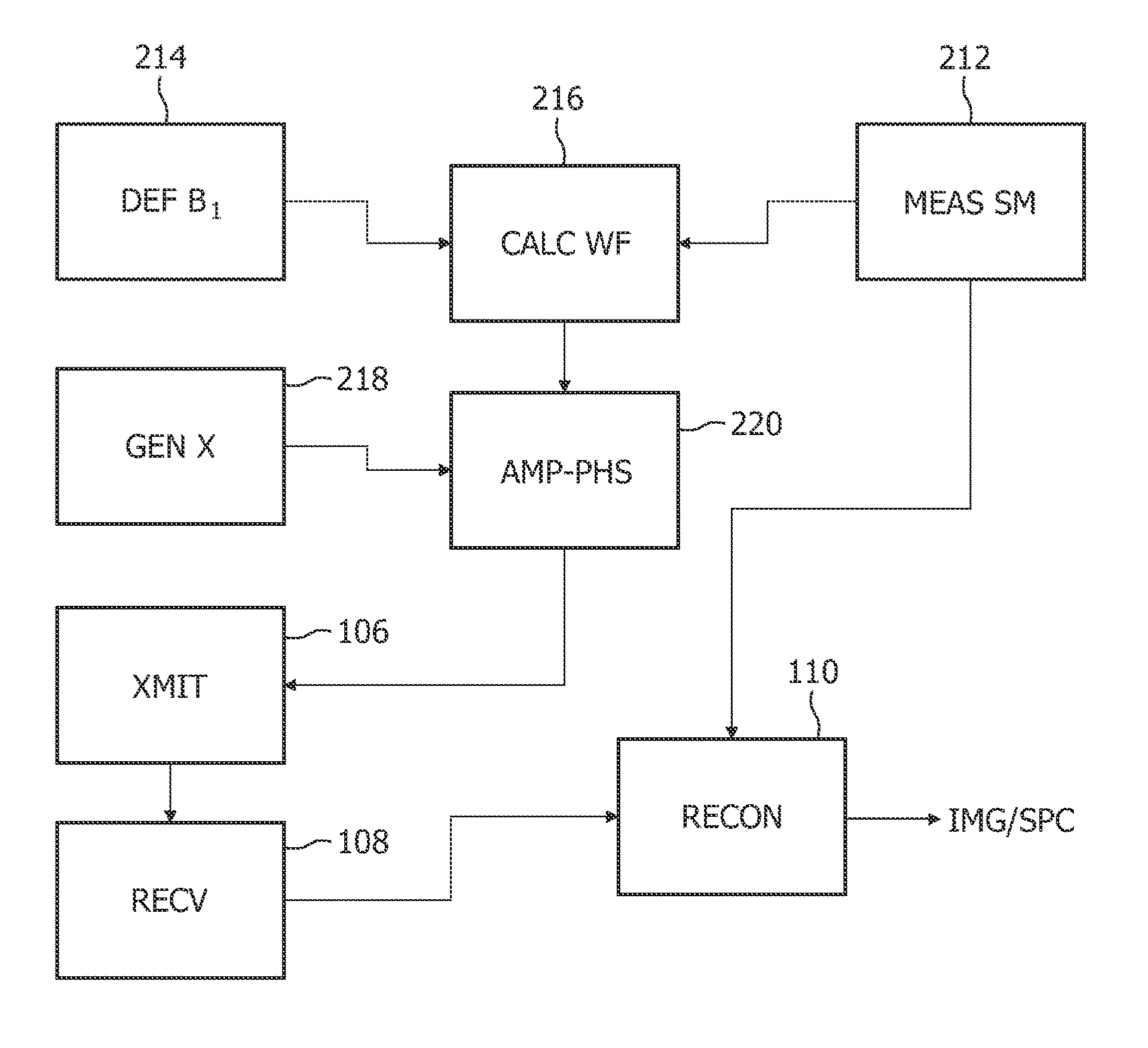
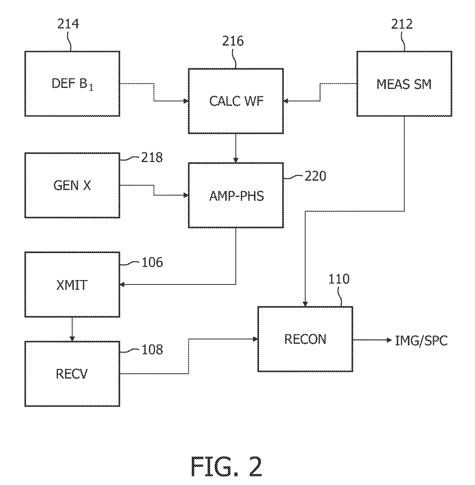
[0017]FIG. 2 diagrammatically shows another embodiment of the method disclosed, wherein the sensitivity map is obtained in a measurement step (MEAS...


PUM


Abstract

A common method of RF encoding assumes that the B1 field generated by the RF coils is linear, which is likely not the case in many situations. It is therefore desirable to have a method of operating an MR system to reconstruct an image of a subject, wherein the method is capable of also handling arbitrary B1 fields used for RF encoding. Accordingly, such an MR system employing one or more RF coils is disclosed herein. The method comprises obtaining transmit sensitivities and weighting factors for individual RF coils. Each RF coil is activated based on its respective weighting factor to apply RF excitation to a subject under examination in the MR system. MR signals—such as free induction decays (FID) signals or echo signals—generated from the subject in response to the RF excitation are received and processed based on the transmit sensitivities to generate an MR image or spectrum representative of the subject.

Description

FIELD OF THE INVENTION[0001]This invention relates to a magnetic resonance (MR) system, particularly to radio-frequency (RF) encoding using one or more RF transmit coils.BACKGROUND OF THE INVENTION[0002]The U.S. Pat. No. 7,701,211 discusses an MR imaging system in which desired RF excitation fields (also referred to as B1 fields) are obtained in a fast and easy way. This object is achieved by a method of operating an MR imaging system, the method comprising the steps of determining complex weighting factors for a plurality of RF coils by measuring the transmit sensitivities of said RF coils and calculating the weighting factors for a given RF excitation, generating a plurality of individual coil drive signals, and individually setting the amplitude and / or phase of each of said coil drive signals according to the respective weighting factor.SUMMARY OF THE INVENTION[0003]RF encoding as performed in the above-mentioned document is based on an assumption of linear B1 fields, i.e., a B1 ...

Claims


Application Information

Patent Timeline
Patent Type & Authority Patents(United States)
IPC IPC(8): G01V3/00
CPCG01R33/3415G01R33/4831
Inventor KATSCHER, ULRICHVERNICKEL, PETERBOERNERT, PETER
Owner KONINK PHILIPS ELECTRONICS NV
Why Eureka
Try Eureka