Optical coherence tomography apparatus and methods

a coherence tomography and optical coherence technology, applied in the field of optical imaging, can solve the problems of difficult interpretation of non-linear scan patterns, complex and expensive mechanisms, and impracticality of many applications

Active Publication Date: 2006-10-26
LIGHTLAB IMAGING
View PDF40 Cites 205 Cited by
  • Summary
  • Abstract
  • Description
  • Claims
  • Application Information

AI Technical Summary

Benefits of technology

[0018] Additional aspects of the invention includes of methods of fabricating the probes and the actuation mechanisms that enable control of the orientation, amplitude, and repetition rate of the scanning beam.
[0019] It should be understood that the terms “a,”“an,” and “the” mean “one or more,” unless expressly specified otherwise.
[0020] The foregoing, and other features and advantages of the invention, as well as the invention itself, will be more fully understood from the description, drawings, and claims which follow.

Problems solved by technology

To the extent that forward-directed optical scanning is possible, such implementations are impractical for many applications.
This follows because they generate non-linear scan patterns that are difficult to interpret, require complex and expensive mechanisms, or require probes with excessively large diameters.
Furthermore, systems that depict actuators and movable mechanisms positioned at or near the distal end of the fiber endoscope conflict with the need to make the distal end as small as possible.

Method used


Image

  • Optical coherence tomography apparatus and methods
  • Optical coherence tomography apparatus and methods
  • Optical coherence tomography apparatus and methods

Examples


Embodiment Construction

[0033] The following description refers to the accompanying drawings that illustrate certain embodiments of the present invention. Other embodiments are possible and modifications may be made to the embodiments without departing from the spirit and scope of the invention. Therefore, the following detailed description is not meant to limit the present invention. Rather, the scope of the present invention is defined by the appended claims.

[0034] It should be understood that the order of the steps of the methods of the invention is immaterial so long as the invention remains operable. Moreover, two or more steps may be conducted simultaneously or in a different order than recited herein unless otherwise specified.

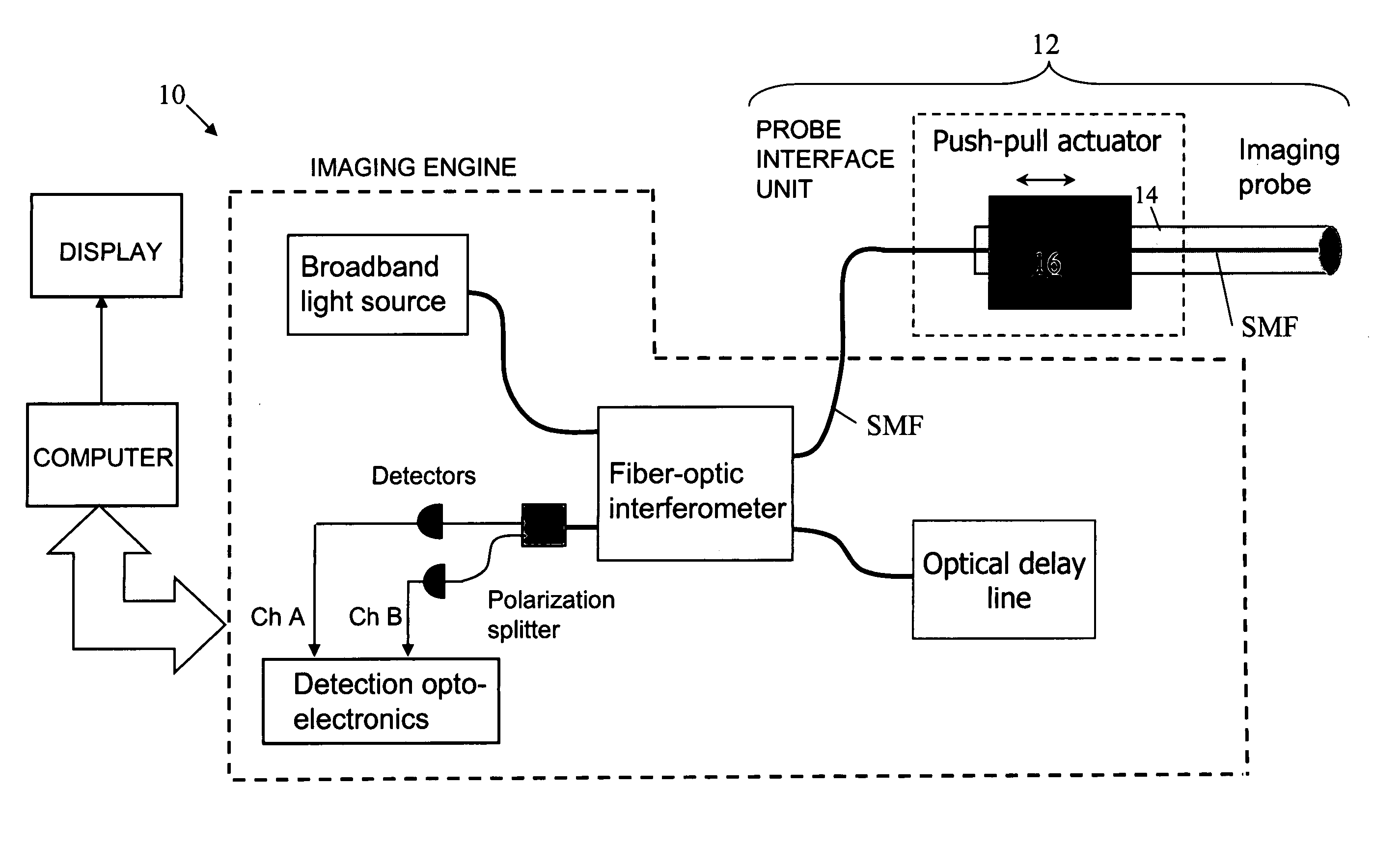
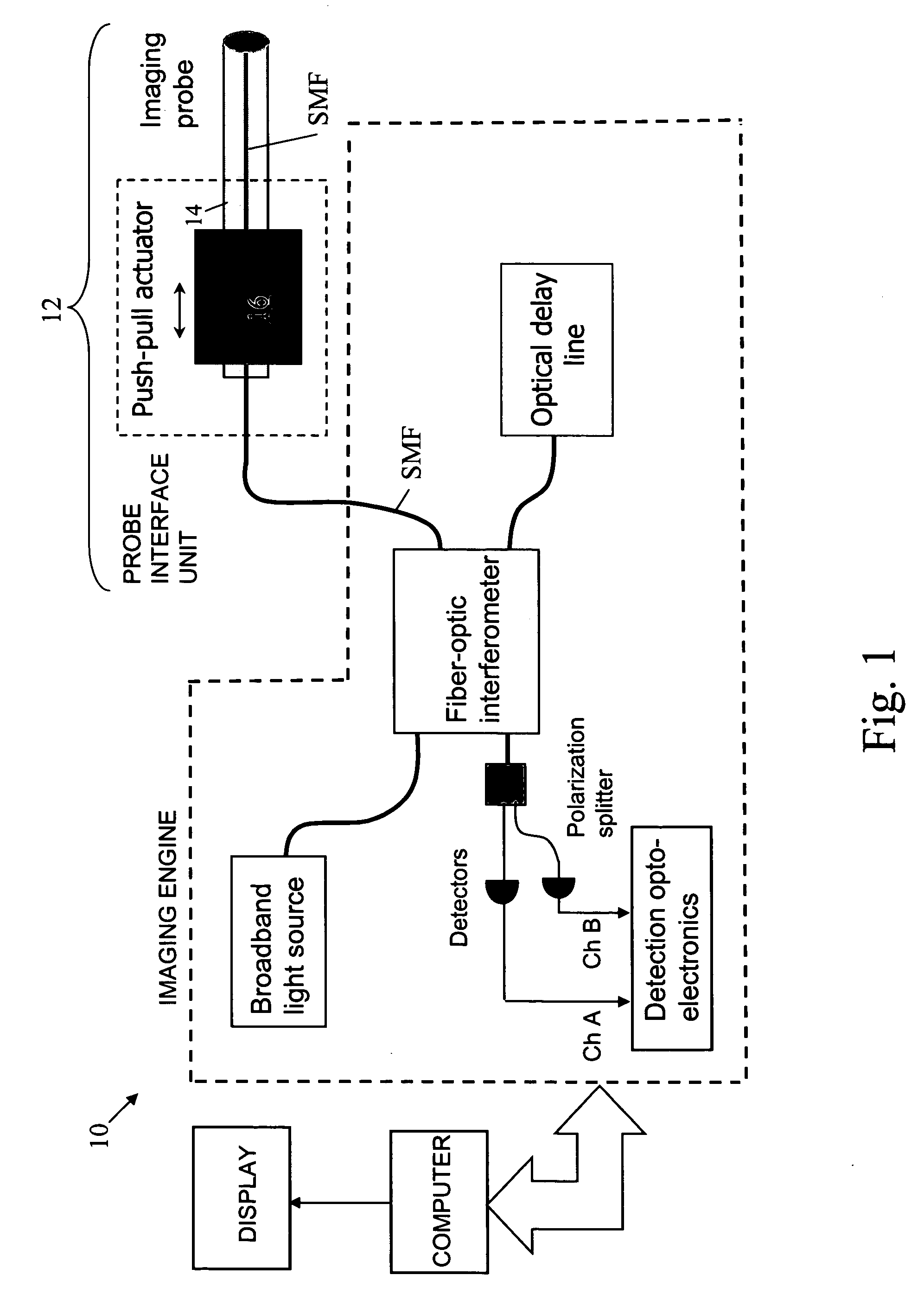
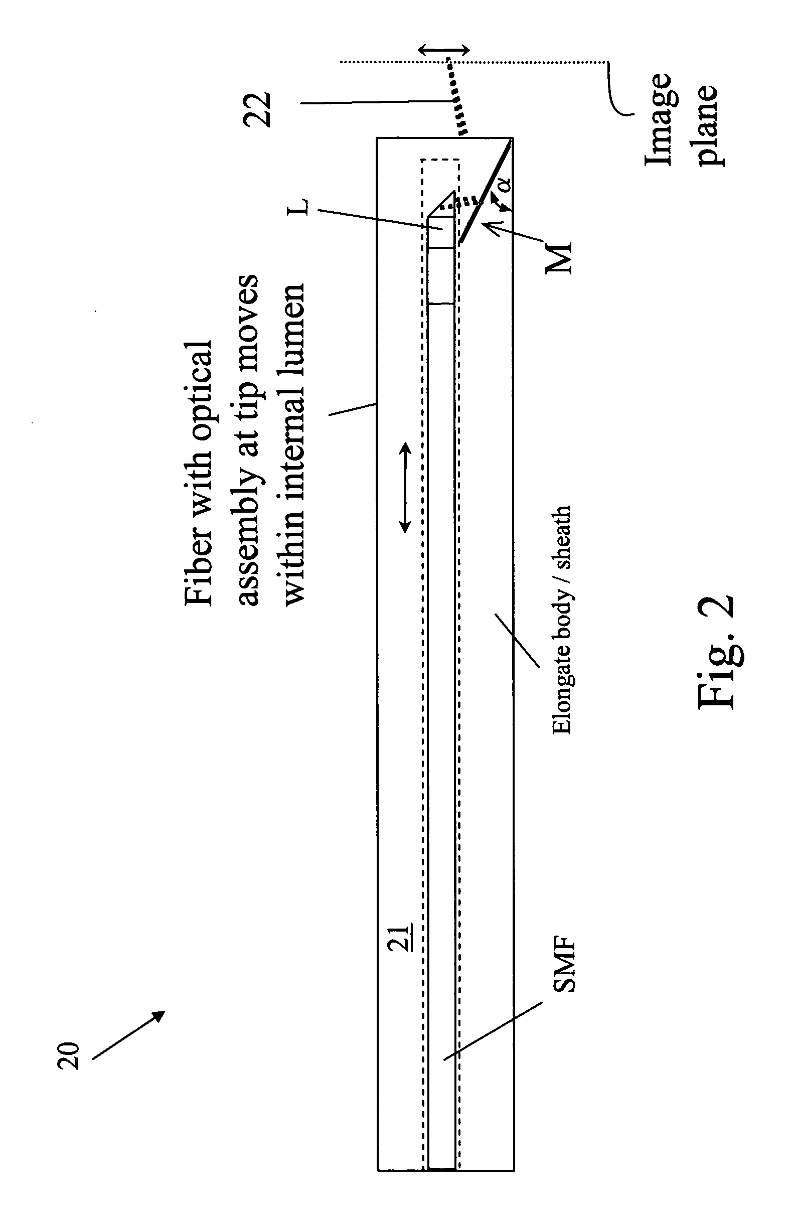
[0035] In general, the aspects and embodiments of the invention disclosed herein relate to imaging system components. Specifically, the aspect of the invention include components, such as probes, push-pull devices, actuators, coils, mechanical linkages and other components s...


PUM


Abstract

In one aspect, the invention relates to an imaging probe. The imaging probe includes an elongate body having a proximal end and distal end, the elongate body adapted to enclose a portion of a slidable optical fiber, the optical fiber having a longitudinal axis; and a first optical assembly attached to a distal end of the fiber. The first optical assembly includes a beam director adapted to direct light emitted from the fiber to a plane at a predetermined angle to the longitudinal axis, a linear actuator disposed at the proximal portion of the elongated body, the actuator adapted to affect relative linear motion between the elongate body and the optical fiber; and a second optical assembly located at the distal portion of the elongate body and attached thereto, the second optical assembly comprising a reflector in optical communication with the first optical assembly, the reflector adapted to direct the light to a position distal to the elongate body.

Description

RELATED APPLICATIONS [0001] This application claims priority to United States Provisional Patent Application 60 / 651,831 filed on Feb. 10, 2005, the disclosure of which is herein incorporated by reference in its entirety.FIELD OF THE INVENTION [0002] This invention relates to the field of optical imaging and more specifically to the design of fiber-optic probes for optical coherence tomography (OCT) and other optical imaging technologies. BACKGROUND OF THE INVENTION [0003] As the demand for less invasive medical diagnosis and treatment grows, techniques for examining living tissue on a microscopic scale have become increasingly important. Conventional medical endoscopes, with diameters that range from about 1 mm to over 1 cm, provide physicians with a view of the surface of the walls of lumens in the gastrointestinal, pulmonary, and reproductive tracts. However, seeing below the surface of the tissue is essential to detect and characterize lesions associated with cancer and other pat...

Claims


Application Information

Patent Timeline
Patent Type & Authority Applications(United States)
IPC IPC(8): A61B6/00
CPCA61B5/0066A61B5/6852G01N21/474G01N21/4795G01N21/8507G01N2021/1787G01B2290/65G01N2021/8528G02B6/262G01B9/0205G01B9/02091G01B2290/70G01N2021/8514
Inventor SCHMITT, JOSEPH M.KOSKI, AMANDAATLAS, MICHAELPETERSEN, CHRISTOPHER
Owner LIGHTLAB IMAGING
Why Eureka
Try Eureka