Mobile unit and control method of mobile unit

a mobile unit and control method technology, applied in the direction of process and machine control, electric controllers, instruments, etc., can solve the problems of difficult control of the above-described way of mobile units

Inactive Publication Date: 2011-11-01
TOYOTA JIDOSHA KK
View PDF15 Cites 30 Cited by
  • Summary
  • Abstract
  • Description
  • Claims
  • Application Information

AI Technical Summary

Benefits of technology

[0025]The present invention can smooth a change in the tilt angle of a vehicle body which occurs during traveling in an inverted pendulum type mobile unit that performs inverted pendulum stabilization control and traveling control based on a velocity target value as an input variable.

Problems solved by technology

Because the above-described handling of the inverted pendulum type mobile unit by the tilt angle of the vehicle body differs significantly from the handling of a passenger car, which controls the velocity of the mobile unit by the adjustment of accelerator opening made by a driver, the above-described way of controlling the mobile unit is generally difficult.

Method used


Image

  • Mobile unit and control method of mobile unit
  • Mobile unit and control method of mobile unit
  • Mobile unit and control method of mobile unit

Examples


first embodiment

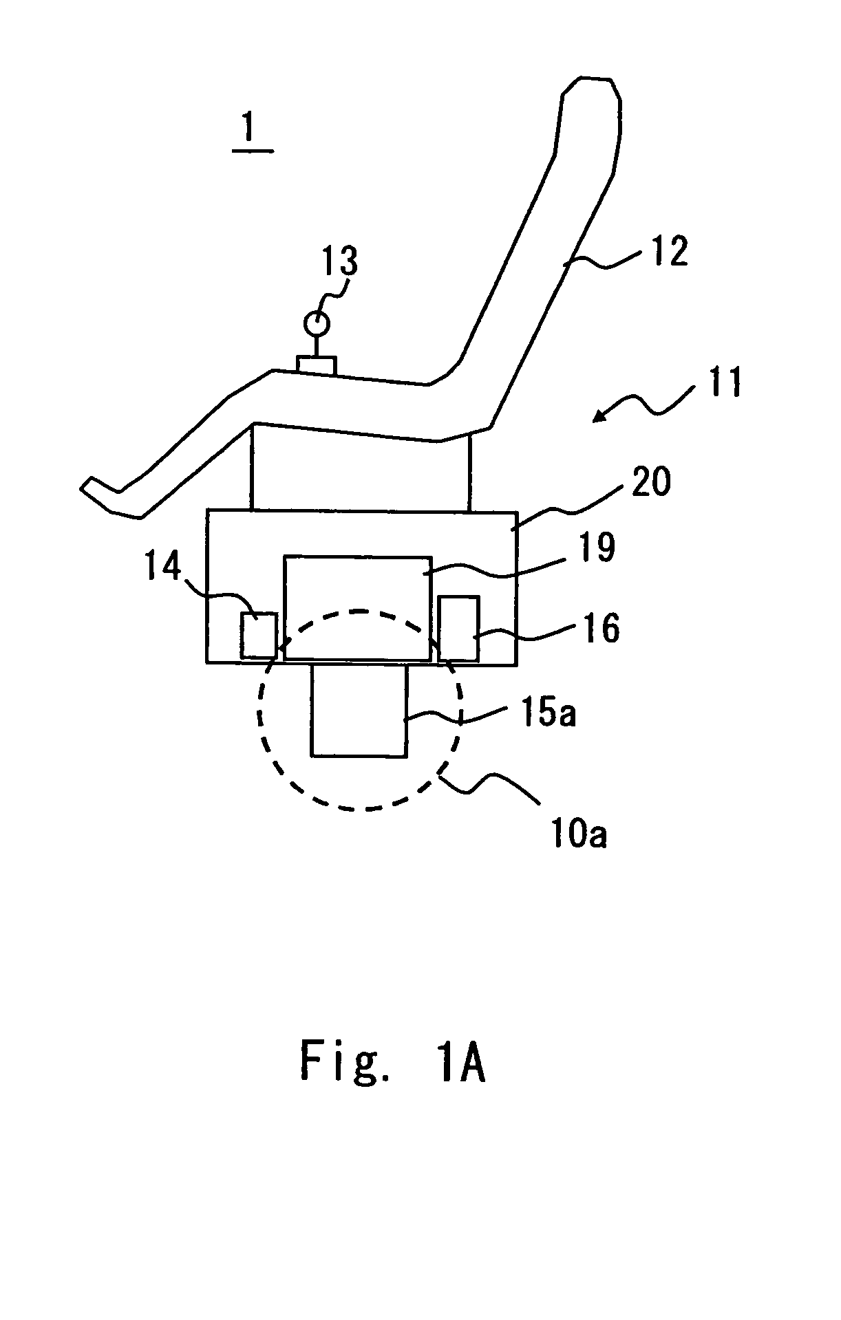
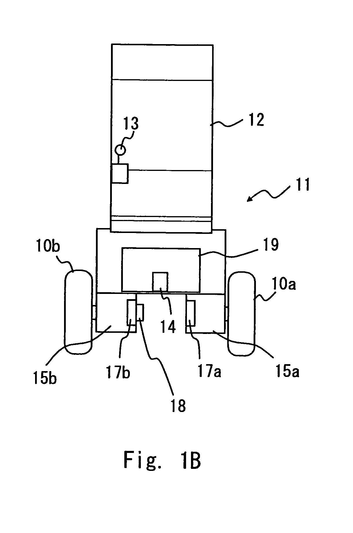
[0059]An inverted pendulum type mobile unit 1 according to an embodiment is a vehicle which is capable of traveling according to the manipulation by a user. The external view of the inverted pendulum type mobile unit 1 (which is referred to hereinafter simply as the mobile unit 1) according to the embodiment is shown in FIG. 1A and FIG. 1B. FIG. 1A is a side view of the mobile unit 1, and FIG. 1B is a front view of the mobile unit 1.

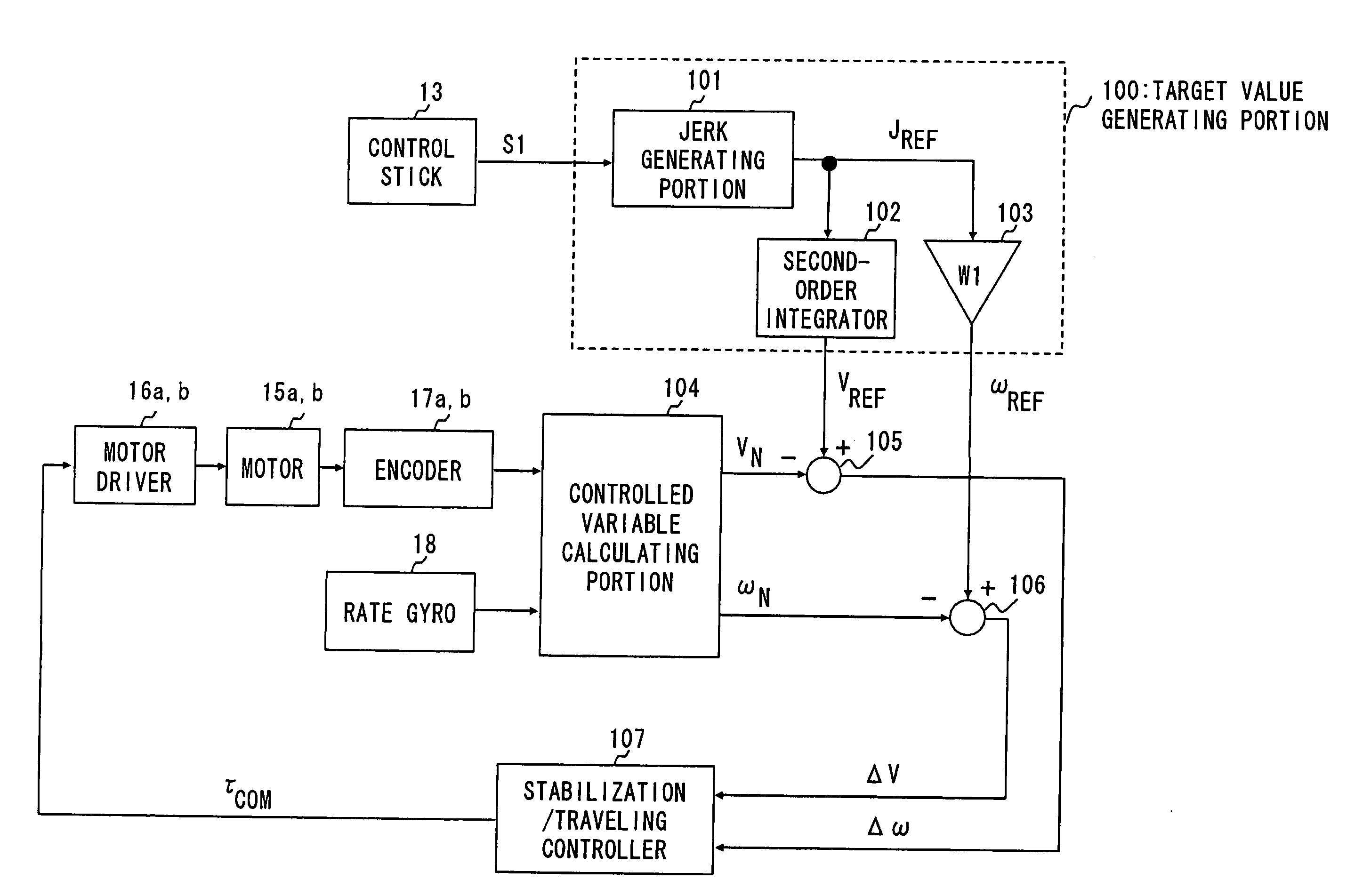
[0060]As shown in FIG. 1A and FIG. 1B, left and right wheels 10a and 10b are placed in the lower part of the mobile unit 1. The wheels 10a and 10b are disposed on the same rotation axis, and a vehicle body 11 can tilt in the longitudinal direction of the mobile unit 1 which is orthogonal to the rotation axis. The vehicle body 11 includes a seat 12, a control stick 13, a computer 14, a motor 15, a motor driver 16, an encoder 17, a rate gyro 18, a battery 19 and a case 20.

[0061]The control stick 13 accepts a manipulation input by a user who is seated on th...

second embodiment

[0095]The mobile body 1 according to the above-described first embodiment of the present invention performs the feedback control using the tilt angular rate target value ωREF that is continuous with respect to time as an input value, thereby suppressing the accidental motion of the vehicle body 11 which is caused by a discontinuous change in tilt angular rate and achieving the smooth tilt motion of the vehicle body 11.

[0096]In order to further smooth the change in the tilt angle of the vehicle body 11, it is desired that a target value of a tilt angular acceleration that is a time derivative of a tilt angular rate target value is continuous with respect to time, that is, the tilt angular rate target value ωREF is time-derivable, in addition to that the tilt angular rate target value ωREF is continuous.

[0097]In order to assure that a target value of a tilt angular acceleration is continuous with respect to time, a velocity target value VREF that is capable of third-order derivative w...


PUM


Abstract

In an inverted pendulum type mobile unit that performs inverted pendulum stabilization control and traveling control based on a velocity target value as an input variable, a change in tilt angle of a vehicle body occurring during traveling is smoothed. The target value generating portion in the inverted pendulum type mobile unit generates the velocity target value VREF of the mobile unit and the tilt angular rate target value ωREF of the vehicle body so that a second-order time derivative of VREF is continuous and ωREF is continuous with respect to time. The controller in the inverted pendulum type mobile unit calculates a torque command value Tcom for the motor drivers using VREF and ωREF as a control target to allow the mobile unit to travel at VREF while maintaining the state where the gravity center of the vehicle body or the gravity center of total mass of the vehicle body and a subject supported on the vehicle body is located above the rotation center of the wheels.

Description

[0001]This is a 371 national phase application of PCT / JP2007 / 067113 filed 28 Aug. 2007, which claims priority of Japanese Patent Application No. 2006-238515 filed 04 Sep. 2006, the contents of which are incorporated herein by reference.TECHNICAL FIELD[0002]The present invention relates to an inverted pendulum type mobile unit and, particularly, to an inverted pendulum type mobile unit which performs inverted pendulum stabilization control and traveling control toward a velocity which is designated by a user or the like as a control target value.BACKGROUND ART[0003]An inverted pendulum type mobile unit in this description includes a vehicle body and a rotator with a circular cross section (such as a wheel) which is coupled to the vehicle body in such a way that the vehicle body can tilt in the longitudinal direction of the mobile unit and is capable of moving by the rotation of the rotator while maintaining the state where the center of gravity of the vehicle body or the center of gr...

Claims


Application Information

Patent Timeline
Patent Type & Authority Patents(United States)
IPC IPC(8): G05D1/08B60L15/00B62K3/00B62K17/00G05B11/36
CPCA61G5/04G05D1/0891A61G2203/14A61G2203/42Y02T10/7258B60L15/20B60L2200/16B60L2260/34B60L2240/12B60L2240/20B60L2240/22B60L2240/423B60L2260/42Y02T10/64Y02T10/72
Inventor YAMADA, KOJI
Owner TOYOTA JIDOSHA KK
Why Eureka
Try Eureka