Calcar planar

a calcar and planar technology, applied in the field of orthopaedics, can solve the problems of affecting the quality of sleeve trial, so as to reduce the risk of bony impingement, avoid and avoid the effect of damage to the top surface of the sleeve trial

Active Publication Date: 2011-11-08
DEPUY PROD INC
View PDF47 Cites 7 Cited by
  • Summary
  • Abstract
  • Description
  • Claims
  • Application Information

AI Technical Summary

Benefits of technology

[0032]The technical advantages of the present invention include the ability of the instrument of the present invention to avoid damage to the top surface of the sleeve trial. For example, according to one aspect of the present invention, an instrument kit is provided for removing calcar bone from the resected face around a bone canal of a femur. The femur may be prepared to receive an orthopedic implant. The instrument kit includes a trial for insertion into the bone canal of the femur and a fixture including a connector for connecting the fixture to the trial, and a guide for guiding the calcar reamer. The calcar reamer is used to remove calcar bone from the resected face around the bone canal of the femur. The calcar reamer includes a feature for cooperation with the guide of the fixture. Thus, the present invention provides for an instrument kit that avoids damage to the top surface of the sleeve trial. The technical advantages of the present invention further include the reduction of risk of bony impingement. For example, according to another aspect of the present invention a method for performing joint arthroplasty is provided. The method includes the steps of resecting a femur to form a resected surface and removing bone from the canal of the femur. The method further includes the steps of inserting a trial to the long bone and determining if bony impingement will occur by having bone superior to the top face of the sleeve trial. If the potential of bony impingement is determined to be a possibility a fixture is attached to the trial and a reamer is guided with the fixture. The method further includes the step of reaming a portion of the resected surface of the femur with the reamer and implanting a neck trial. Thus, the present invention provides for the reduction of risk of bony impingement.
[0033]The technical advantages of the present invention further include the ability to precisely remove excess bone. For example, according to another aspect of the present invention, a fixture for removing calcar bone from the resected face around the bone canal of a femur is provided. The fixture includes a connector for connecting the fixture to the trial and a guide for guiding the calcar reamer. The calcar reamer includes a feature, for example, a bulb on the distal portion of the reamer. The bulb contacts the upper face of the sleeve and sets a precise distance between the reamer cutting surface and the top face of the sleeve such that the excess bone is precisely removed. Thus, the present invention provides for precisely removing excess bone from around the resected face of a femur.
[0034]The technical advantages of the present invention further include the ability to obtain accurate leg length of the stem. For example, according to yet another aspect of the present invention, a kit for removing calcar bone from a resected face around a bone canal of a femur is provided. The kit includes a fixture including a connector for connecting the fixture to the trial and a guide for guiding the calcar reamer. The trial including a sleeve is positioned in the canal of the femur and the trial and sleeve are precisely set to obtain an accurate leg length of the stem. The calcar reamer thus removes excess reamer around the resected face of the long bone such that proximal neck component of the trial stem accurately seats against the distal trial component such that an accurate trial assembly is used to perform a trial reduction. An implant for insertion in the long bone is then placed into the canal. Thus, the present invention provides for obtaining accurate leg length of the stem.

Problems solved by technology

Such patients of joint replacement surgery typically suffer from osteoarthritis or rheumatoid arthritis.
The top surface of the sleeve trial may be scraped or defaced to the point that metal shavings are released into the patient and the size etchings on the sleeve trials may become illegible.

Method used


Image

  • Calcar planar
  • Calcar planar
  • Calcar planar

Examples


Embodiment Construction

[0068]Embodiments of the present invention and the advantages thereof are best understood by referring to the following descriptions and drawings, wherein like numerals are used for like and corresponding parts of the drawings.

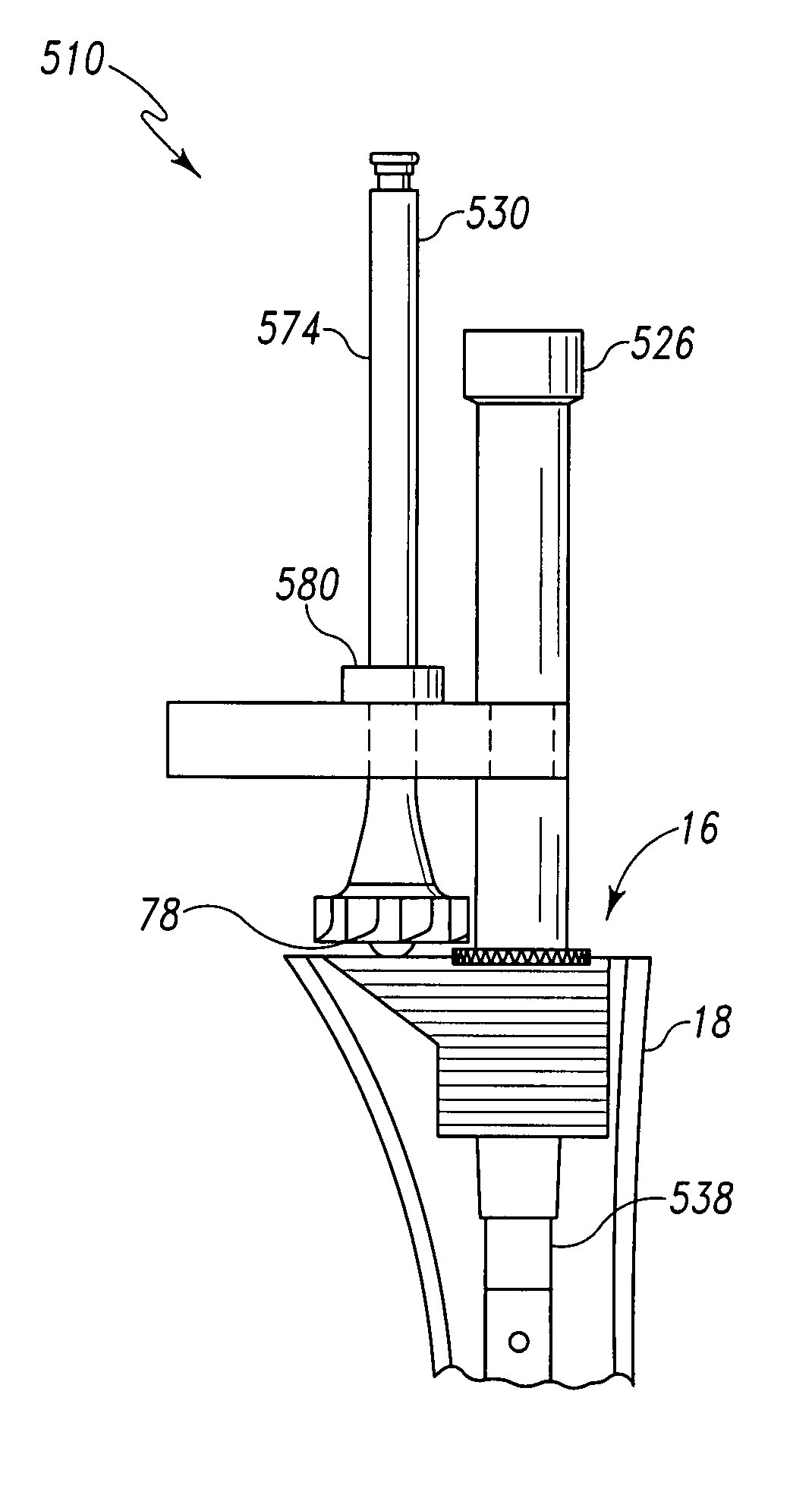
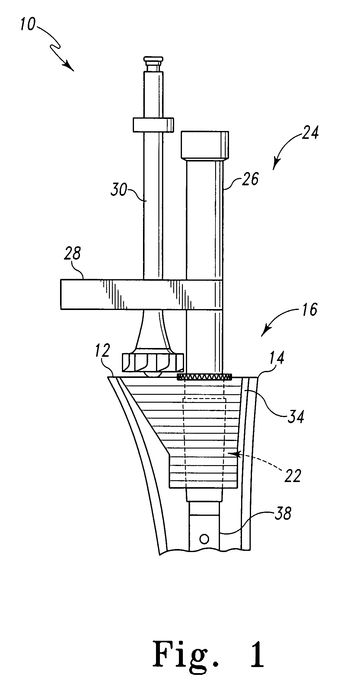
[0069]According to the present invention and referring now to FIG. 1, a kit 10 for removing calcar bone 12 from a resected face 14 around a bone canal 16 of a long bone, for example, a femur 18 is shown. The long bone 18 is prepared to receive an orthopedic implant 20.

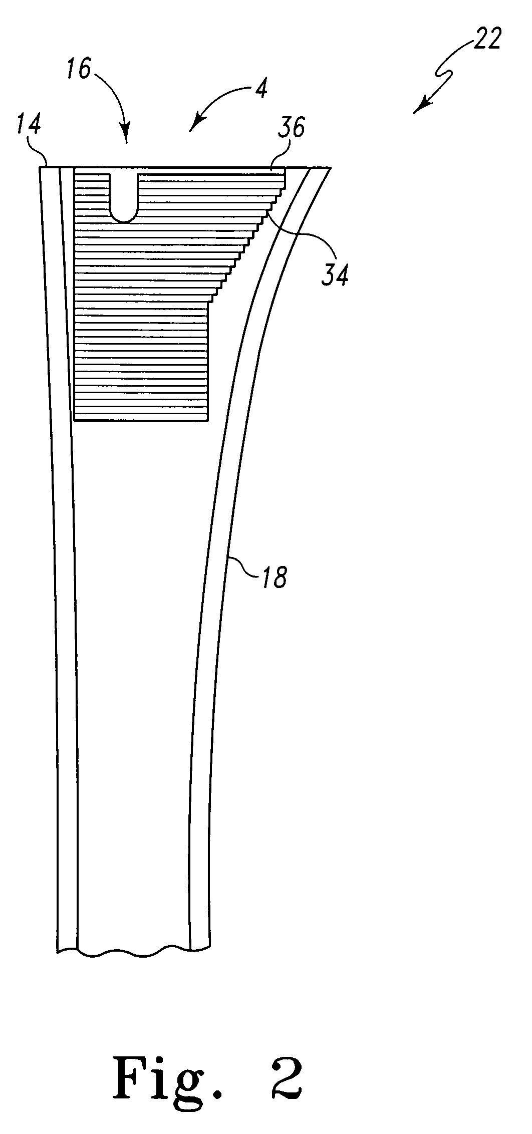
[0070]The kit 10 includes a trial 22 for insertion into the bone canal 16 of the femur 18. The kit 10 further includes a fixture 24 including a connector 26 for connecting the fixture 24 to the trial 22. The fixture 24 further includes a guide 28.

[0071]The kit 10 includes a calcar reamer 30 for reaming calcar bone 12 from the resected face 14 around the bone canal 16 of the femur 18. The calcar reamer 30 includes a feature 32 for cooperation with the guide 28 of the fixture 24.

[0072]Referring now...


PUM


Abstract

A kit for removing calcar bone from a resected face around a bone canal of a long bone prepared to receive an orthopaedic implant is provided. The kit includes a trial for insertion into the bone canal of the long bone and a fixture. The fixture has a connector for connecting the fixture to the trial and a guide for guiding the calcar reamer. The kit also includes a calcar reamer for removing calcar bone from the resected face around the bone canal of the long bone. The reamer includes a feature for cooperation with the guide of the fixture. The kit further includes an implant for insertion into the bone canal of the long bone.

Description

TECHNICAL FIELD OF THE INVENTION[0001]The present invention relates generally to the field of orthopaedics, and more particularly, to an implant for use in arthroplasty.BACKGROUND OF THE INVENTION[0002]Joint replacement surgery is quite common and it enables many individuals to function properly when they otherwise would not be possible to do so. Such patients of joint replacement surgery typically suffer from osteoarthritis or rheumatoid arthritis. Artificial joints usually comprise metallic, ceramic and / or plastic components that are fixed to existing bone.[0003]Such joint replacement surgery is otherwise known as total joint arthroplasty. Total joint arthroplasty is a well-known surgical procedure by which a diseased and / or damaged joint is replaced with a prosthetic joint. In a typical total joint arthroplasty, the ends or distal portions of the bone adjacent the joint are resected or a portion of the distal part of the bone is removed and the artificial joint is secured thereto...

Claims


Application Information

Patent Timeline
Patent Type & Authority Patents(United States)
IPC IPC(8): A61B17/00A61B17/58A61F5/00
CPCA61B17/1668A61B17/175A61F2/4684A61B2017/1602A61F2/30734A61F2/32A61F2/34A61F2/3662A61F2/367A61F2/3676A61F2002/30322A61F2002/30604A61F2002/30616A61F2002/30738A61F2002/30827A61F2002/30904A61F2002/3495A61F2002/3611A61F2002/3625A61F2002/365A61F2002/3686A61F2250/0026
Inventor SACKETT, SAMUEL G.CARR, JONATHAN E.DEBOER, DAVID K.
Owner DEPUY PROD INC
Why Eureka
Try Eureka