
Low noise, highly linear amplifying stage and signal receiver using the same

a high-linear, amplifier technology, applied in power management, transmission monitoring, wireless communication, etc., can solve the problems of insufficient noise performance of variable gain amplifier in fig. 1, insufficient noise performance of system b>199/b> in fig. 1, and insufficient linearity performance, etc., to achieve high-linear, continuous or discrete gain control, good noise performance

Active Publication Date: 2011-11-08
MACRONIX INT CO LTD
View PDF10 Cites 23 Cited by
  • Summary
  • Abstract
  • Description
  • Claims
  • Application Information

AI Technical Summary

Benefits of technology

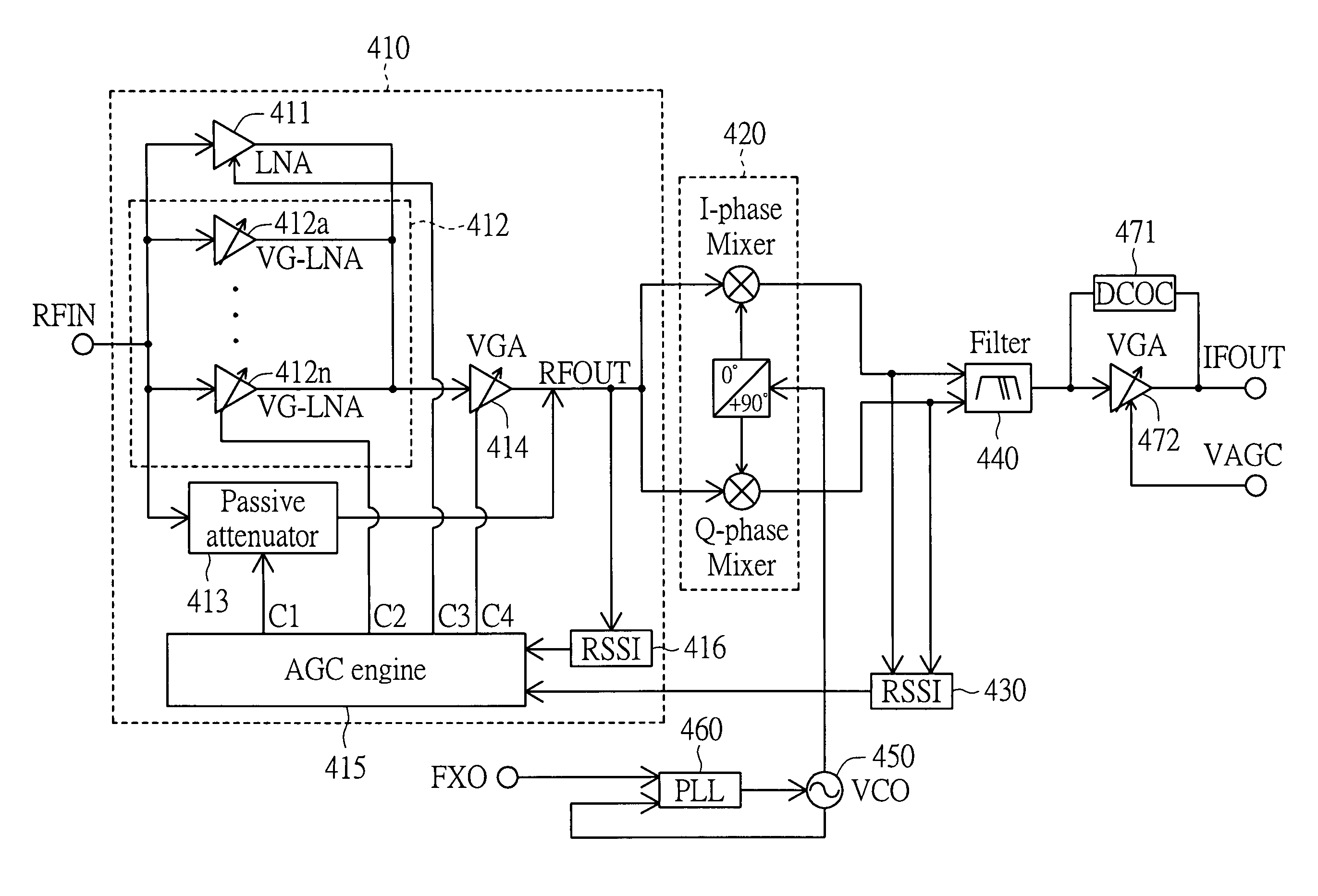
[0014]The present invention is directed to a RF signal amplifying stage for amplifying RF signals with highly linear, continuous or discrete gain control and good noise performance by combining active fixed-gain LNA, active VG-LNA array and passive attenuator.
[0015]The present invention is directed to a signal receiver for amplifying signals with highly linear, continuous or discrete gain control and good noise performance by combining active fixed-gain LNA, active VG-LNA array and passive attenuator in a front-end amplifying stage.

Problems solved by technology

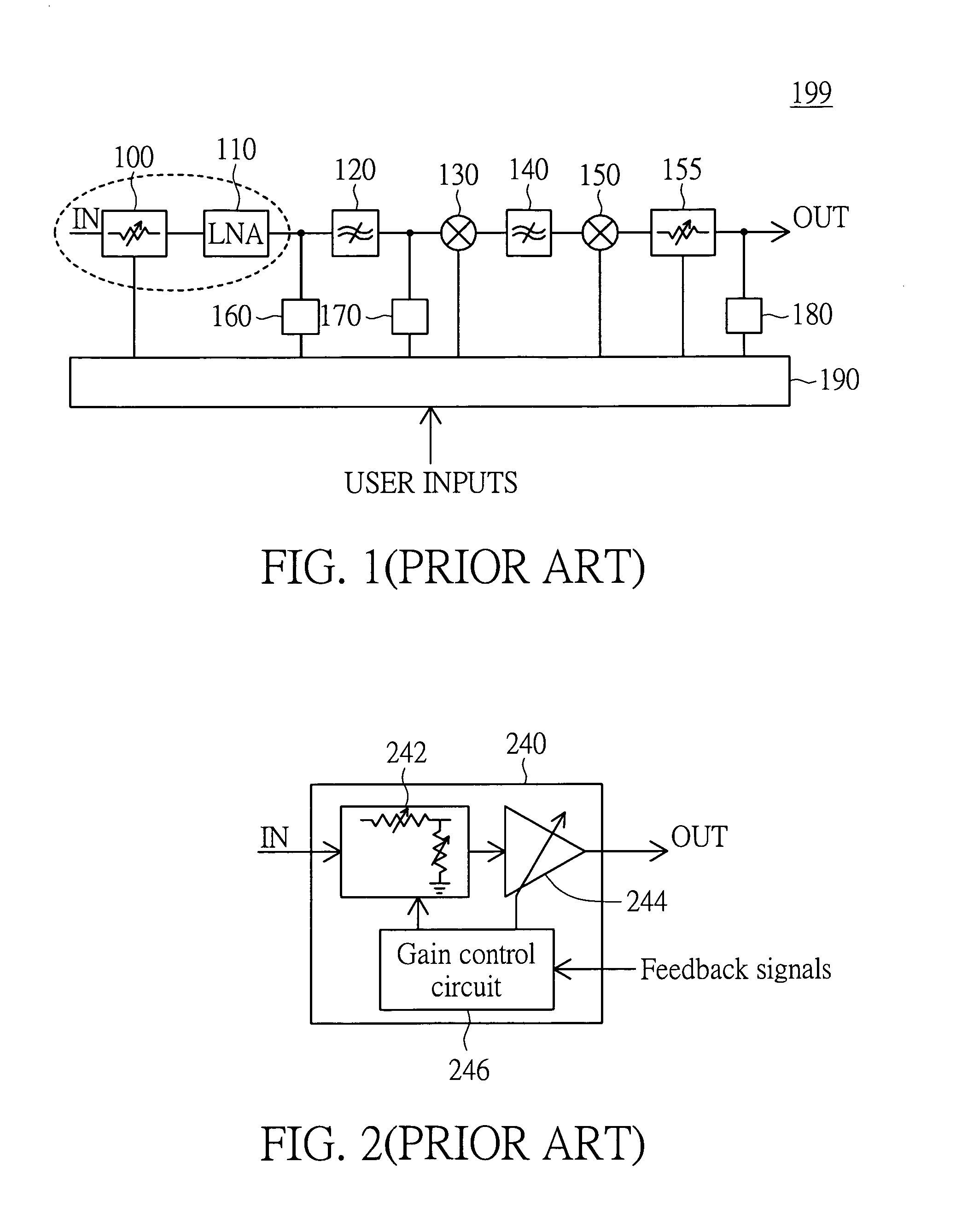
That is, Applicant perceives that the noise performance of the system 199 in FIG. 1 is not good enough.
That is, Applicant perceives that the noise performance of the variable gain amplifier 240 in FIG. 2 is not good enough.
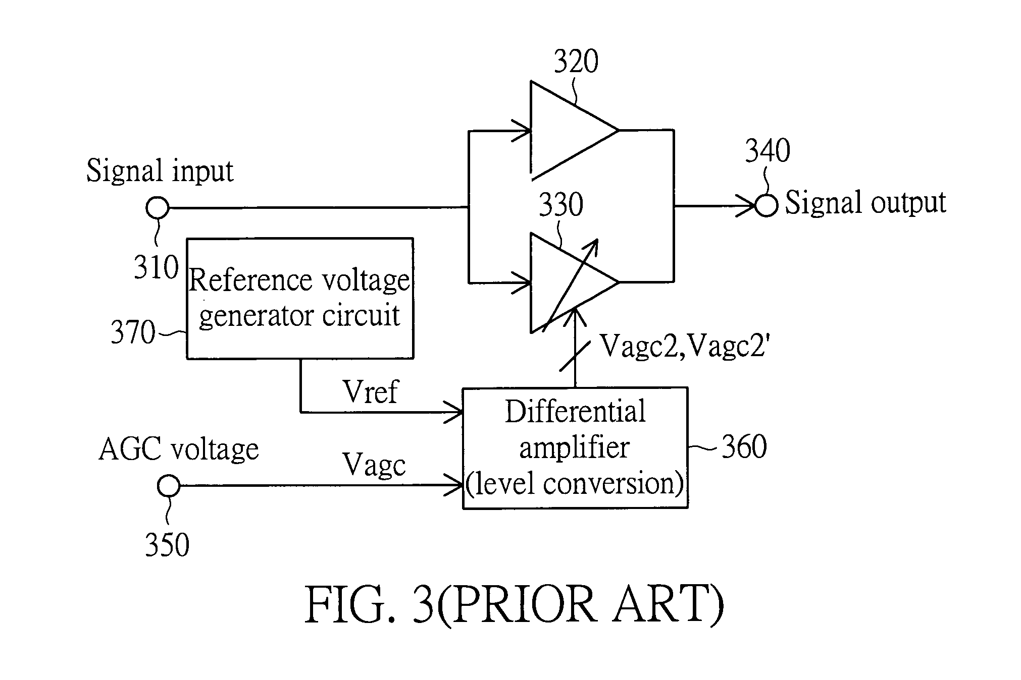
Further, during normal operation, either the active fixed-gain LNA 320 or the active VGA 330 will be active, so Applicant perceives that the linearity performance is also limited.
However, it is difficult to design a very linear amplifying stage capable of amplifying large input signals in a linear fashion which simultaneously possesses continuous or discrete gain control.
A further complication is the desire to implement a relatively large dynamic range over which gain control operates.

Method used


Image

  • Low noise, highly linear amplifying stage and signal receiver using the same
  • Low noise, highly linear amplifying stage and signal receiver using the same
  • Low noise, highly linear amplifying stage and signal receiver using the same

Examples


Embodiment Construction

[0025]Reference will now be made in detail to the present preferred embodiments of the invention, examples of which are illustrated in the accompanying drawings. Wherever possible, the same reference numbers are used in the drawings and the description to refer to the same or like parts.

[0026]An embodiment of the invention provides a receiver implementing a wide dynamic range, continuous or discrete gain control and low noise figure. The disclosed receiver is for example, configured to operate as a television receiver in a system. The system, applying the disclosed receiver, can be a television, television receiver, set top box, or television tuner integrated within a video recorder or some other television receiver. In other embodiments, the system can be a radio receiver, wireless transceiver, telephone receiver, cellular telephone, cordless telephone, or some other communication device.

[0027]The signal receiver disclosed in the embodiment of the invention can be coupled to one or...


PUM


Abstract

The invention provides a signal amplifying stage, used in a signal receiver. The signal amplifying stage has: a fixed-gain low noise amplifier (LNA), amplifying an input signal; a variable-gain LNA (VG-LNA) array, amplifying the input signal, including a plurality of parallel VG-LNAs, the VG-LNA array being parallel with the fixed-gain LNA; a variable-gain amplifier (VGA), being in series with the fixed-gain LNA and the VG-LNA array, for amplifying output signals from the fixed-gain LNA and the VG-LNA array to generate an output signal; an attenuator, being in parallel with a combination of the fixed-gain LNA, the VG-LNA array and the VGA, for attenuating the input signal to generate the output signal; and a control loop, coupled to the VGA and the attenuator, for detecting power levels of the output signal to enable and control the fixed-gain LNA, the VG-LNA array, the VGA and the attenuator.

Description

BACKGROUND OF THE INVENTION[0001]1. Field of the Invention[0002]The present invention generally relates to a low noise, highly linear amplifying stage and a signal receiver using the same, which have wide dynamic range and good noise performance by combining active amplifiers and passive attenuators.[0003]2. Description of Related Art[0004]In telecommunication systems, RF (radio frequency) signals or input signals can be distributed to destination devices over a wide area using, for example wireless communication links or wireline communication links. Signal receivers may select between wireless signals received or wireline signals received. In general, wireless signals received are much weaker than wireline signals received. The received signals strength at the receivers may vary over a wide range due to the different characteristics of the wireless links and the wireline links.[0005]TV tuners, which is a kind of signal receivers, need to provide both low noise and highly linear (i...

Claims


Application Information

Patent Timeline
Patent Type & Authority Patents(United States)
IPC IPC(8): H04B1/06
CPCH03G3/3052H04W52/52
Inventor HUANG, YI-TI
Owner MACRONIX INT CO LTD
Learn More