Method for removing surgically implanted devices

a technology of surgical implants and implants, which is applied in the field of surgical implant removal methods, can solve the problems of imposing risk, discomfort and potential tissue damage on the patient, and achieve the effects of reducing the risk of infection, and improving the safety of patients

Active Publication Date: 2011-11-08
ALFRED E MANN FOUND FOR SCI RES
View PDF1 Cites 22 Cited by
  • Summary
  • Abstract
  • Description
  • Claims
  • Application Information

AI Technical Summary

Problems solved by technology

If there is a problem with the function or location of the microstimulator, then additional surgery must be performed to remove or relocate the microstimulator, imposing risk, discomfort and potential tissue damage to the patient.

Method used


Image

  • Method for removing surgically implanted devices
  • Method for removing surgically implanted devices
  • Method for removing surgically implanted devices

Examples


Embodiment Construction

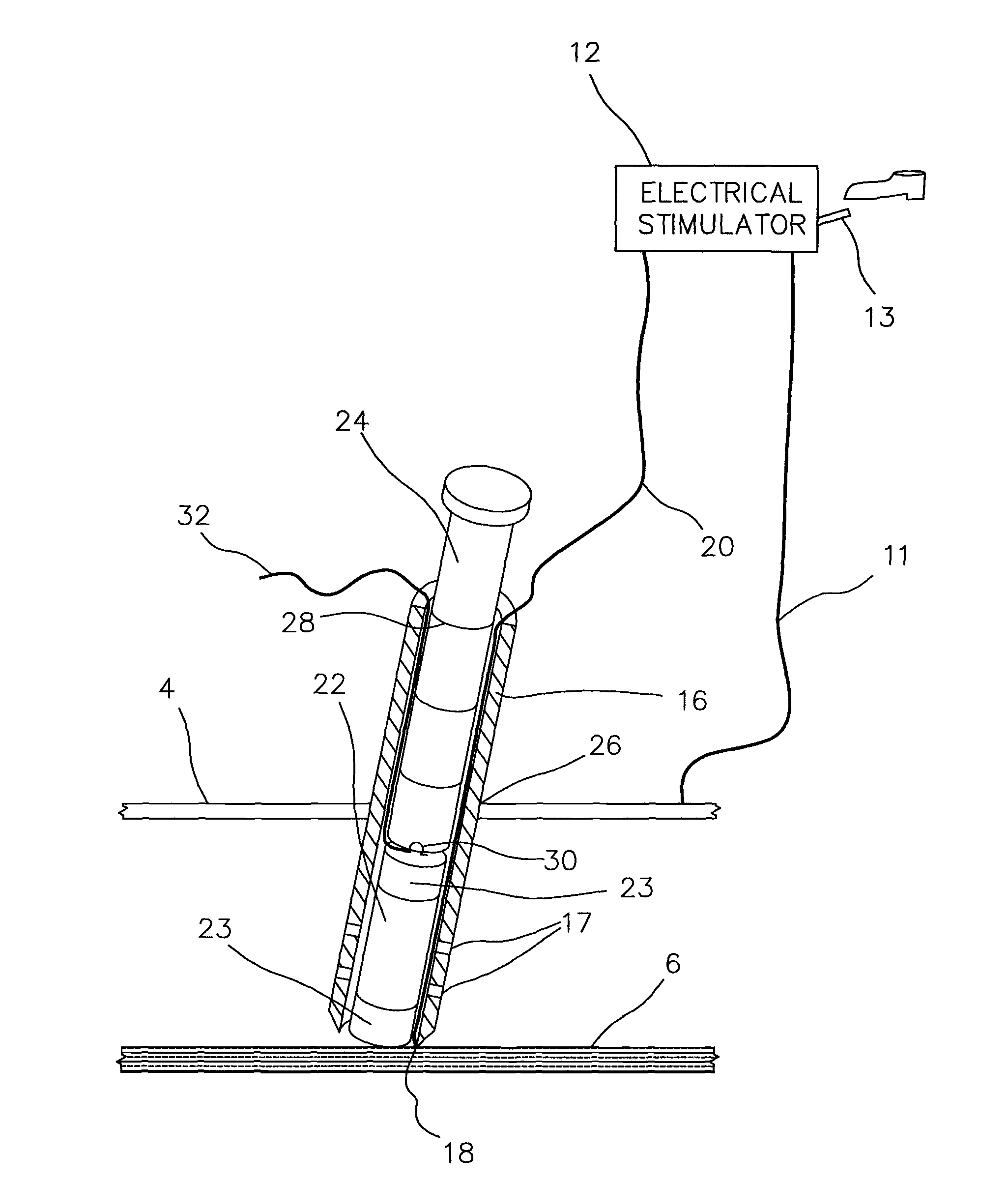
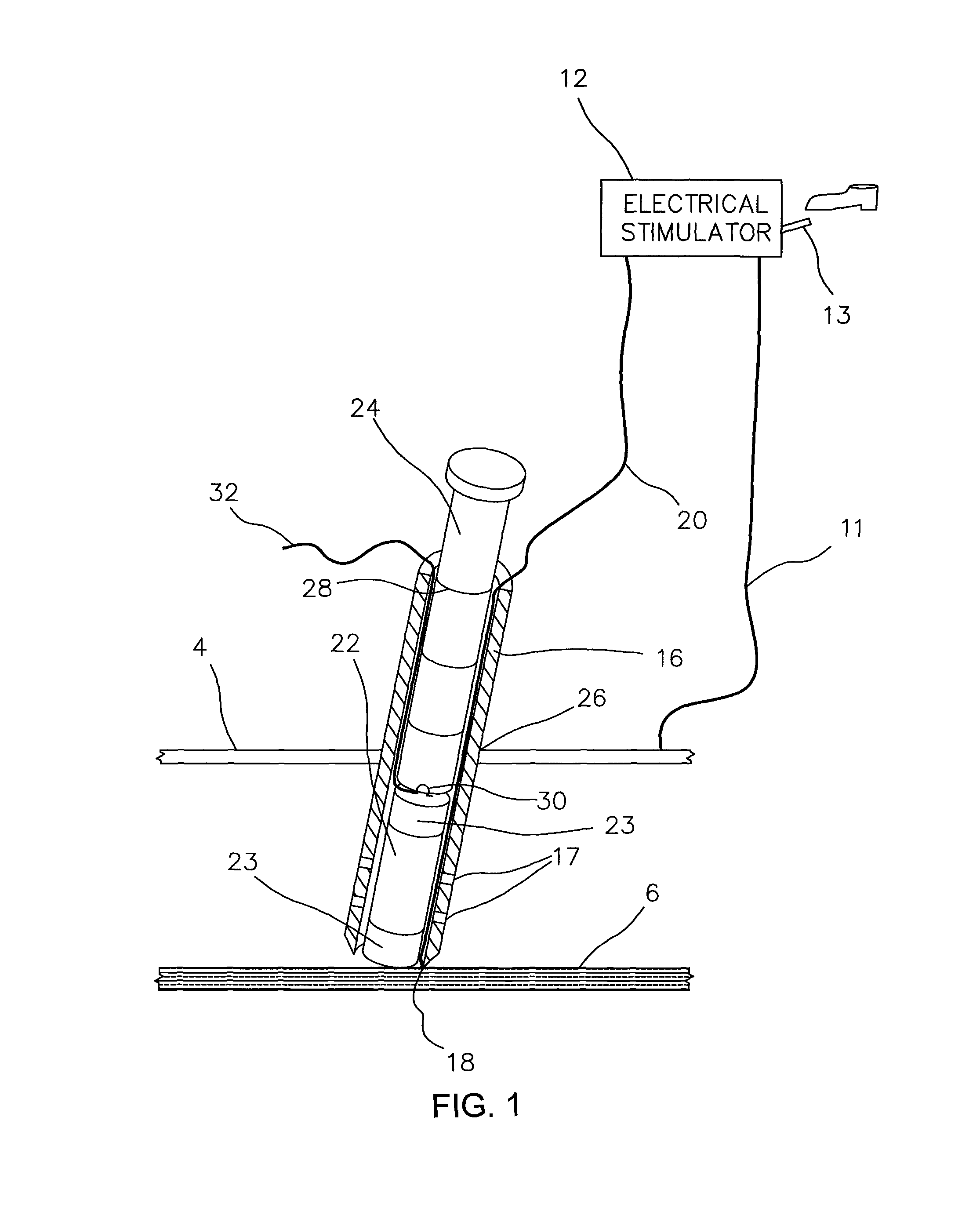
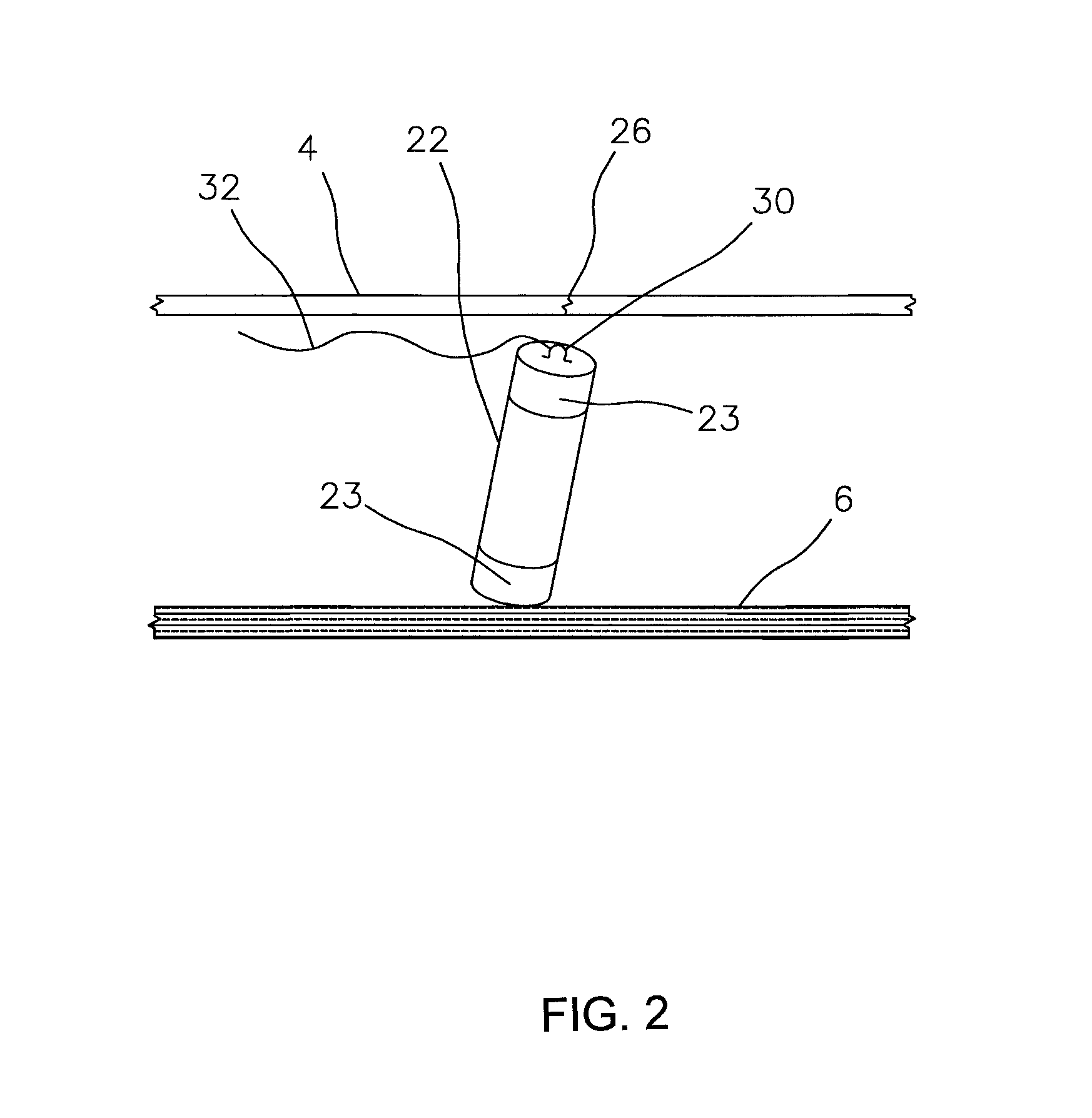
A microstimulator 22 (see FIG. 2) is represented by a small tubular device that contains an electronic package and communication means for modifying or affecting a body parameter when it is located near a nerve 6 or muscle to be stimulated. The nerve 6 is a specific targeted beneficial nerve that is selected because it controls a specific desired muscular function. In a preferred embodiment, the microstimulator 22 has microstimulator electrodes 23 located on each end.

FIG. 1 illustrates the microstimulator 22 being inserted into the outer sheath 16 using the blunt-end push rod 24. Alternately, the microstimulator can be inserted into the outer sheath 16 by using the electrode probe 2 or inner sheath 8. The blunt-end push rod 24 has a location mark 28 that circumscribes the push rod 24 such that the location of the microstimulator 22 in the outer sheath 16 can be ascertained by reference to the location mark 28.

Once the microstimulator 22 is placed in close communication with the nerv...


PUM


Abstract

A method of removing an implantable electronic microdevice by an integral removal loop or circumferential ring to facilitate removal of the implanted microdevice without additional surgery. The device is removed by pulling it along the surgically created implantation path. Optionally a radio-opaque tether provides a method of locating the implantable microdevice without additional surgery and attachment of one end of the tether to a radio-opaque marker provides a method of locating the end of the tether to facilitate removal of the implantable microdevice from living tissue.

Description

BACKGROUND OF THE INVENTIONMicrostimulators are small, surgically implantable electrical microdevices that pass a small electrical signal to living tissue in order to elicit a response from a nerve or muscle. Microsensors are similar electrical microdevices except that they detect electrical and other signals that are generated by living tissue. The term microstimulator is intended to apply equally to both microstimulators and microsensors. The use of microstimulators or microsensors which are implanted in living tissue to stimulate a muscle function by either stimulating a nerve or the muscle itself are well known. The microstimulators receive power and control signals by inductive coupling of magnetic fields generated by an extracorporeal antenna rather than requiring any electrical leads. See for example, U.S. Pat. Nos. 5,193,539; 5,193,540; 5,324,316; 5,405,367; 6,175,764; 6,181,965; 6,185,452; 6,185,455; 6,208,894; 6,214,032; and 6,315,721, each of which is incorporated in its ...

Claims


Application Information

Patent Timeline
Patent Type & Authority Patents(United States)
IPC IPC(8): A61N1/05
CPCA61B5/6882A61N1/0551A61N1/36003A61N1/372A61N1/37205A61N2001/0578
Inventor SCHULMAN, JOSEPH H.ZILBERMAN, YITZHAKPURNELL, KATE E.VOGEL, MARTIN J.VOGEL, LEGAL REPRESENTATIVE, ADAM
Owner ALFRED E MANN FOUND FOR SCI RES
Why Eureka
Try Eureka