Gas turbine engine and method for reducing turbine engine combustor gaseous emission

a gas turbine engine and combustor technology, applied in the field of turbine engines, can solve the problems of large combustor space, large catalyst space, and undesirable compounds in combustion systems, and achieve the effect of reducing the combustor size or weight of the combustor without increasing the size or weight of the combustor

Active Publication Date: 2011-11-15
AIRBUS SAS
View PDF9 Cites 32 Cited by
  • Summary
  • Abstract
  • Description
  • Claims
  • Application Information

AI Technical Summary

Benefits of technology

[0020]By injection of hydrogen, combustion kinetics is accelerated, so that the combustor size can be small even for low turbine engine power conditions without the risk of un-burnt hydrocarbon and carbon monoxide emissions. Thus, a smaller combustor size can be used without a negative effect for low turbine engine power. The smaller combustor size is advantageous for high turbine engine power conditions to minimize NOX emissions. For high power output operation and a mid-power output operation, hydrogen injection may be stopped to reduce consumption of hydrogen.
[0038]The invention can be applied to gas turbine engines for aeronautics, marine applications and industrial power production. However, the invention is most particularly appropriate for aviation, because aircraft turbine engines are routinely operated at low power for extended periods of times. For example, aircraft engines run at low power while taxiing. Hence, the invention is particularly useful for reducing gaseous emissions of aircraft turbines at airports or the like.

Problems solved by technology

Generally, these combustion systems may emit undesirable compounds such as nitrous oxide compounds (NOX) and carbon-containing compounds.
Such known gas turbine engines have the disadvantage that the catalysts are heavy and take up considerable space within the combustor chamber.
Hence, the whole arrangement is bulky, heavy and complicated.
Such turbine engines exhibit high pressure and high temperature at combustor inlets during high power operations.
This is detrimental to NOX emissions.
In addition, environmental concerns have led, and are likely to lead, to more and more stringent NOX certification requirements.

Method used


Image

  • Gas turbine engine and method for reducing turbine engine combustor gaseous emission
  • Gas turbine engine and method for reducing turbine engine combustor gaseous emission
  • Gas turbine engine and method for reducing turbine engine combustor gaseous emission

Examples


Embodiment Construction

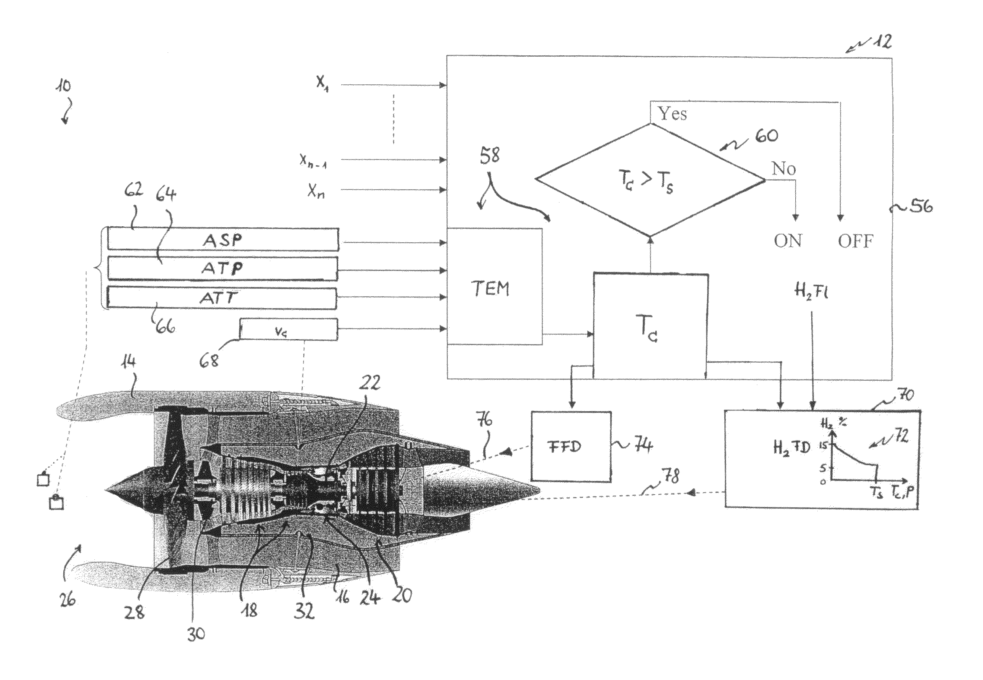
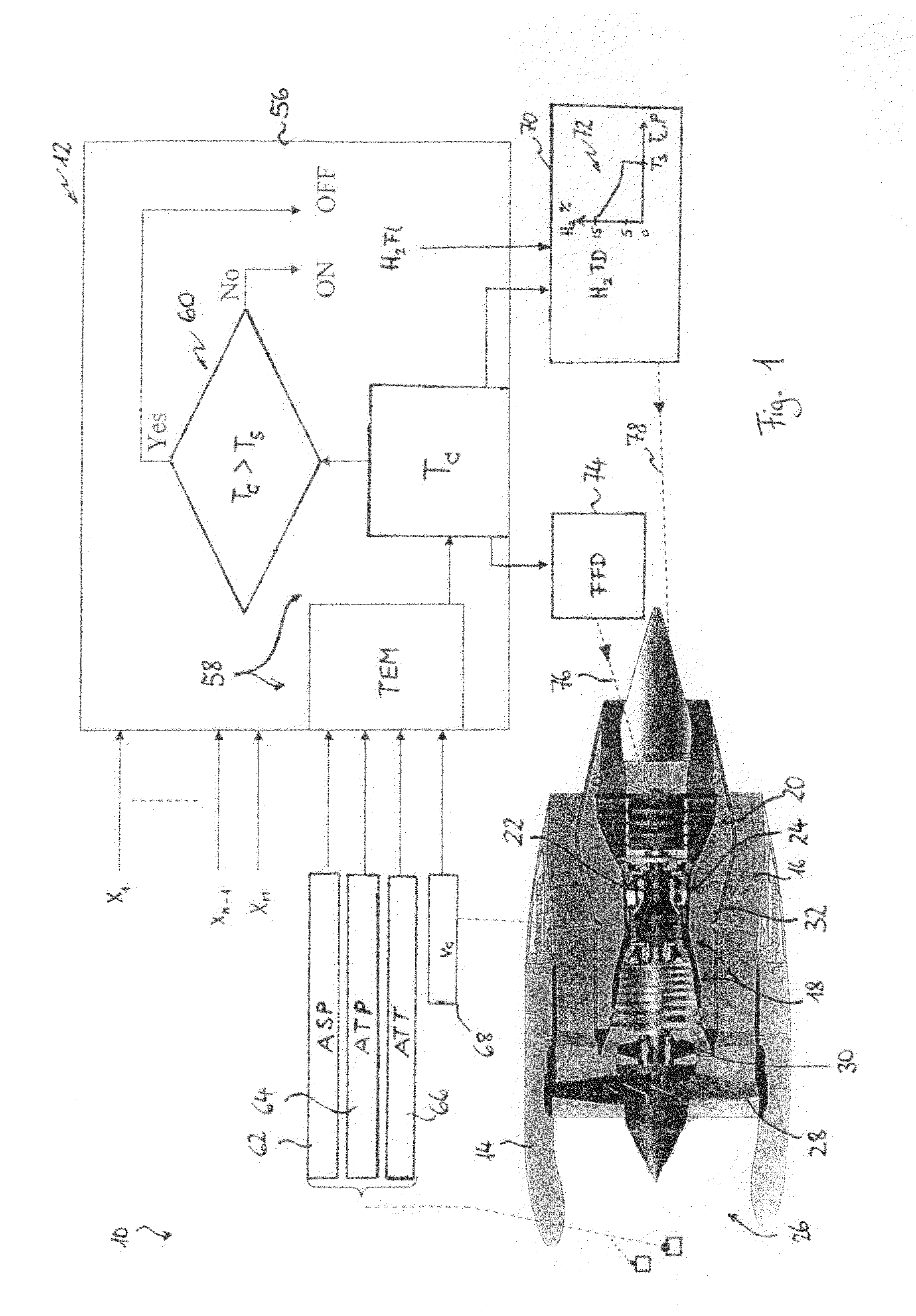
[0045]FIG. 1 shows a gas turbine engine 10 with a turbine engine control system 12. The gas turbine engine 10 is adapted to be used as an aviation turbine engine and includes an outer housing 14 with a bypass duct 16; a compressor 18; a turbine 20; a core rotor 22 joining the compressor 18 and the turbine 20; and an annular combustor 24 between the compressor 18 and the turbine 20. At an inlet 26 of the housing 14, a fan 28 is connected to the core rotor 22. The compressor 18, the turbine 20 and the core rotor 22 form the core 30 of the gas turbine engine 10 which is enclosed by an inner housing 32. The inner housing 32 is surrounded by the bypass duct 16.

[0046]The compressor 18 compresses air entering the housing 14 through the inlet 26 and discharges the pressurized air to the combustor 24. In the combustor 24, the pressurized air is mixed with fuel. The air / fuel mixture is ignited to generate hot combustion gas which flows downstream from the combustor through the turbine 20. The...


PUM


Abstract

In a turbine engine hydrogen is injected into the combustor in response to a power output level of the turbine engine. In a preferred embodiment, gaseous hydrogen is always injected at low-power operations and switched off at mid-power and high-power operations.

Description

FIELD OF THE INVENTION[0001]The present invention relates generally to turbine engines used in aeronautics but also to turbine engines for industrial and marine applications. More specifically, the present invention refers to a reduction of gaseous emissions of gas turbine engines.BACKGROUND OF THE INVENTION[0002]A gas turbine engine includes a core having a compressor fixedly joined to a turbine by a core rotor extending axially therebetween. At least one combustor, for example an annular combustor or a plurality of combustor chambers distributed around the core, are disposed between the compressor and the turbine and include fuel injectors. The fuel injectors may be joined to a fuel control valve which meters fuel into the at least one combustor during operation.[0003]The compressor includes one or more stages of circumferentially spaced apart compressor rotor blades and cooperating compressor stator vanes through which air is channeled during operation for increasing the pressure...

Claims


Application Information

Patent Timeline
Patent Type & Authority Patents(United States)
IPC IPC(8): F02C3/22F02C9/26F02C9/28F02C7/22
CPCF02C3/30F02C9/28F23N1/002F23R3/36F05D2270/082F23R2900/00002F23N2041/20F23C2900/9901F23N2241/20
Inventor REMY, SEBASTIENBOTTI, JEAN
Owner AIRBUS SAS
Why Eureka
Try Eureka