
Multi-task-tool
a multi-tasking, tool technology, applied in the storage of work tools, wrenches, screwdrivers, etc., can solve the problems of confusion of intended installation and even removal, and achieve the effect of positive control
- Summary
- Abstract
- Description
- Claims
- Application Information
AI Technical Summary
Benefits of technology
Problems solved by technology
Method used
Image

Examples
Embodiment Construction
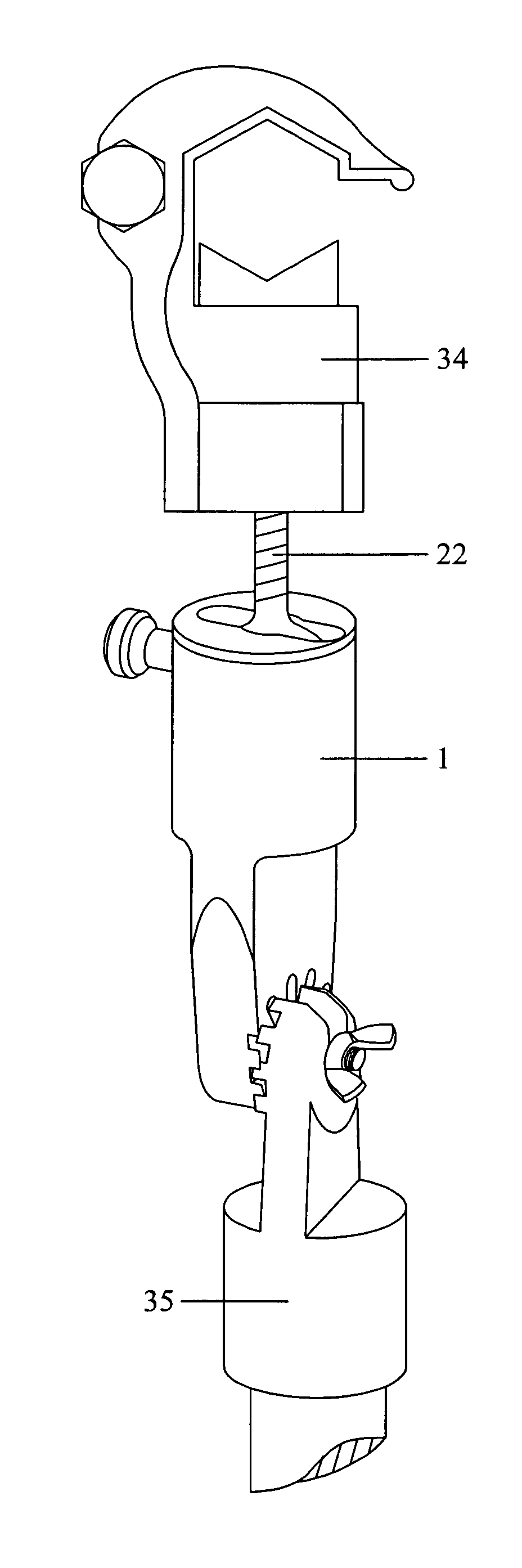
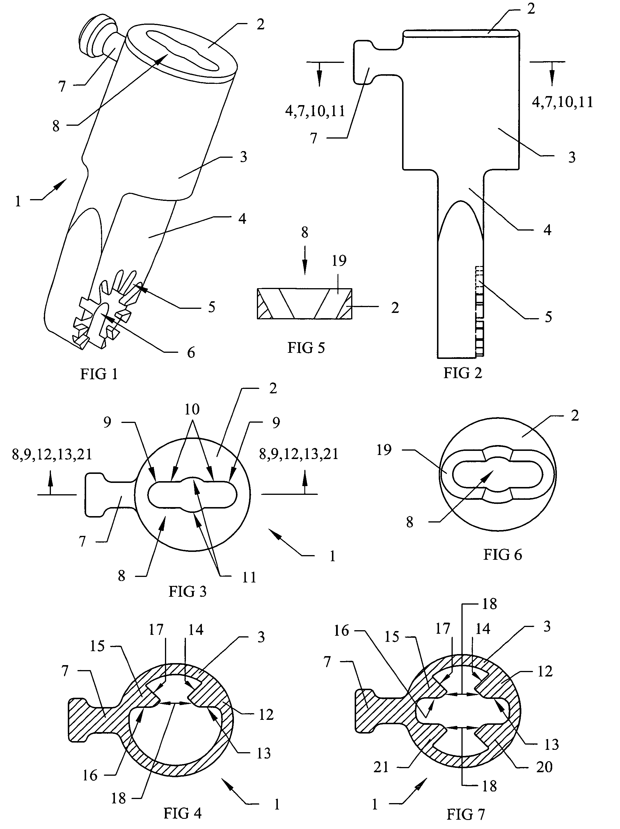
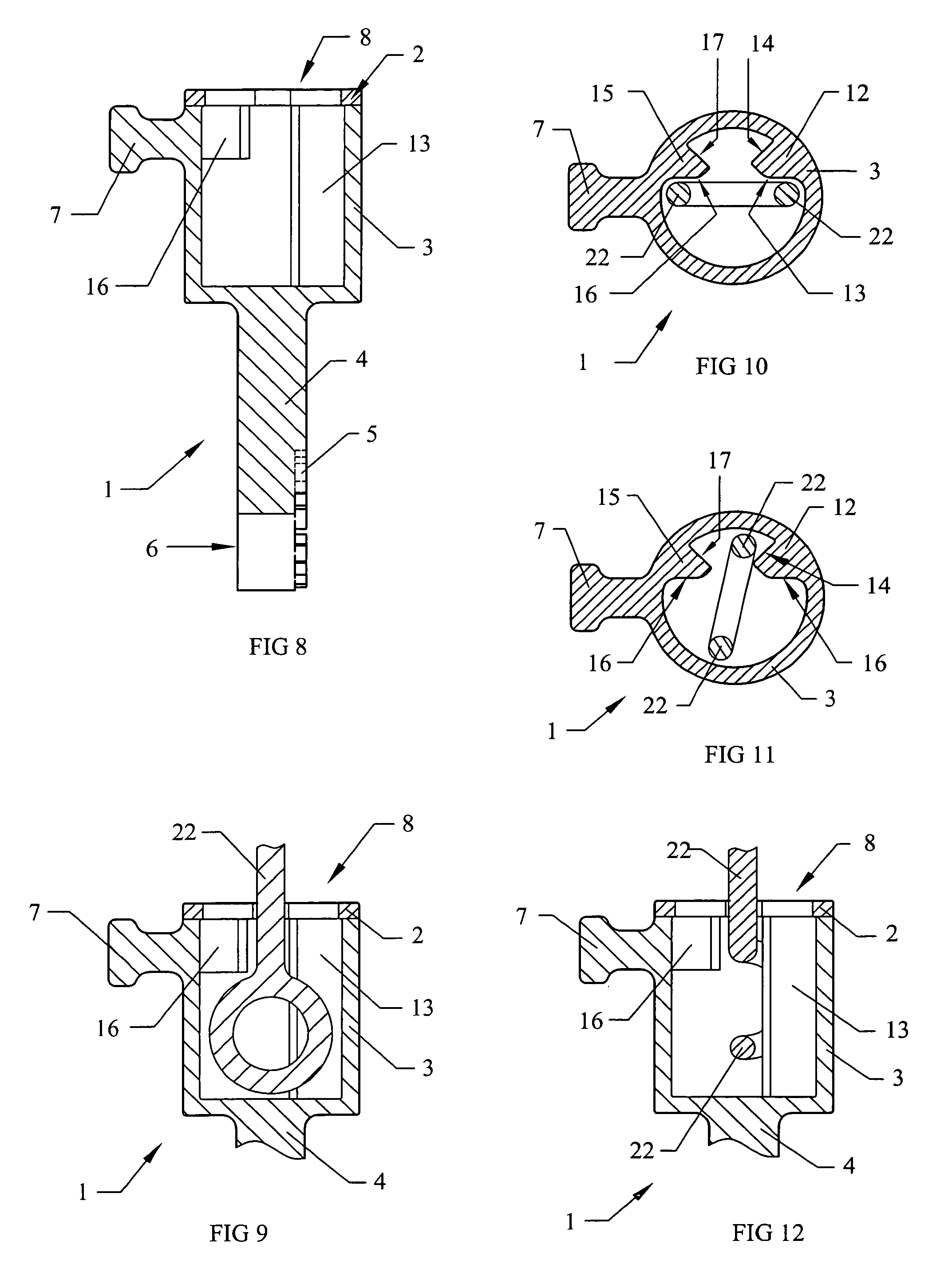
[0053]FIGS. 1-4 and FIGS. 8-12 Show various views of the first embodiment of Multi-Task-Tool 1 consisting of an elongated cylindrical body 3 which defines a bore diameter that accommodates slide ably receiving the eye of an eye bolt or winged fastener. An aperture cap 2 defining a centrally located radius end 9 elongated aperture 8 with two parallel long edges 10 further defining central opposing shank radiuses 11 is attached across one end of the body. The device also includes a mounting base 4 attached or unitary to the body 3 at the opposite end from the aperture cap 2. The body 3 contains internally opposing long rail 12 and a short rail 15 within its bore having long rail first flat surface 13 and short rail first flat surface 16 together defining a plane having a first end aligned with and proximal to one long edge 10 of aperture cap 2. The rails central edges define rail slot 18 and respectively have long rail second flat surface 14 and short rail second flat surface 17 behin...
PUM
 Abstract
Description
Claims
Application Information