
Grip-over knife

a technology of cutting knives and grippers, which is applied in the field of gripping knives, can solve the problems of limited fine control over the movement and cutting action of such knives, the inability of knives to provide great variability in intended gripping, and the inability of commonly used culinary knives to provide fine control of the cutting action. to achieve the effect of improving the user experience of available cutting actions

Inactive Publication Date: 2009-05-28
CHAMBLESS III THOMAS STROUD +1
View PDF26 Cites 2 Cited by
  • Summary
  • Abstract
  • Description
  • Claims
  • Application Information

AI Technical Summary

Benefits of technology

[0011]The object of the present invention is to be a novel culinary knife and cutlery unit that enhances the user experience of available cutting actions in multiple ways as follows:
[0013]The object of the present invention is to provide a high degree of fine user control of the knife. This fine control may also be thought of as dexterous use of the knife. This is intended to be accomplished largely in two ways. First, the digits are able to be applied for gripping the knife in such fashion as to exert a novel degree of fine control over movements and direction. This is due to the digits exerting collective and autonomous pressure on the knife that is usable to control position and movement of the knife, and force applied to the knife. Second, the entirety of the grip is to be above and in close proximity to the blade, allowing a variety of methods of applying force and control to the knife, enabling enhanced control of knife movement and cutting.

Problems solved by technology

Also, due to the distance between the handle and the blade, and the effort needed to orient and move the knife to desired positions, the degree of fine control over the movement and cutting action of such knives is limited.
However, such knives are usually not very effective for finely controlled culinary cutting applications such as slicing or carving.
Commonly used culinary knives do not provide great variability in intended gripping.
While users may modify their grip of such knives by applying the hand closer to the blade edge or onto part of the spine of the blade, this is not apparently intended by the handle structure of such knives.
Users can have trouble manipulating a standard culinary knife which often has total length almost twice as long as the user hand, often up to about fifteen inches.

Method used


Image

  • Grip-over knife
  • Grip-over knife

Examples


Embodiment Construction

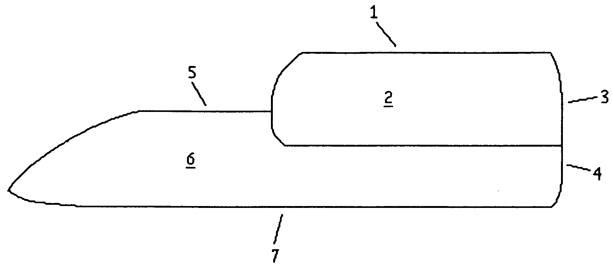
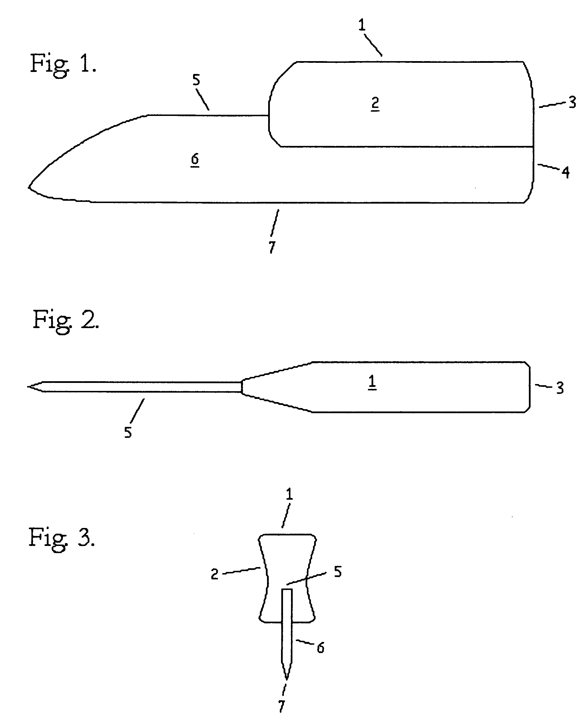
[0020]In reference to the drawings, FIGS. 1-3 illustrate from the side, top, and front the construction of our invented knife unit as herein described. The present invention is a novel culinary knife unit comprising an elongated blade 6 and an elongated handle 2 generally parallel to each other, having the total length of the handle joined longitudinally onto and contiguously connected directly against and over the spine 5 of the blade 6. This invention has no aperture or other opening between the handle 2 and blade 6. The present invention is intended to be used as a food cutter knife for use for raw or cooked foodstuff preparation.

[0021]The blade 6 of the present invention is made having a usable sharpened cutting edge 7 as one elongated perimeter and an elongated blunt spine 5 as its elongated perimeter side opposite the cutting edge 7. The spine 5 and cutting edge 7 join at the distal front end of the blade 6 in a manner suitable for making a culinary knife. This joining at the ...


PUM


Abstract

The present invention is a culinary knife, intended for one handed use, comprising a handle and a blade having a cutting edge as its bottom perimeter. The entire length of the handle of the knife is joined contiguously against the spine of the blade leaving no aperture between them. This joining of the handle and blade results in the user gripping onto rather than around the handle of the knife. The handle does not extend beyond the rear of the blade, thus the user grips the knife above part of the cutting edge. This provides the user the ability to apply direct downward force for cutting and provides enhanced ability to use the palm and digits to apply finely directed force and movement to the knife. Both the location of the user hand and its proximity to the blade further enhance fine control and ease of use of the knife.

Description

BACKGROUND OF THE INVENTION[0001]The present invention is a culinary knife and cutlery unit intended to be used for the cutting of foodstuffs which are placed on a cutting board or other foodstuff supporting surface.[0002]Commonly used existing culinary knives, and other such knives which we are aware of, each have specific limitations. For example, the chef's knife and similar knives with the handle extended rearward of the blade are useful for carving and slicing foodstuffs, but usable to apply force directly down from the handle to the blade as is optimal for chopping. Also, due to the distance between the handle and the blade, and the effort needed to orient and move the knife to desired positions, the degree of fine control over the movement and cutting action of such knives is limited.[0003]In contrast to the chef's knife and similar knives, the mezzaluna and similar culinary instruments are able to receive direct downward force for effective cutting, which is especially usefu...

Claims


Application Information

Patent Timeline
IPC IPC(8): B26B3/00
CPCB26B3/00
Inventor CHAMBLESS, III, THOMAS STROUDCHAMBLESS, JEFFREY STROUD
Owner CHAMBLESS III THOMAS STROUD
Learn More