Electrical switch with positive status indication

a technology of status indication and electric switch, which is applied in the direction of electric switch, tumbler/rocker switch, electric apparatus, etc., can solve the problems of tight requirements on the strength of the locking device, malfunctioning locking mechanism, and limit the maximum force that the device can withstand, so as to prolong the life and withstand large forces

Inactive Publication Date: 2008-12-18
EATON ELECTRIC INC
View PDF2 Cites 2 Cited by
  • Summary
  • Abstract
  • Description
  • Claims
  • Application Information

AI Technical Summary

Benefits of technology

[0005]The present invention aims to provide a robust switch that never gives a false “OFF” indication, also not when the contacts are welded, and has a long lifetime. The invention aims at providing a construction which can withstand large forces without damaging the switch and especially without the risk of damaging the contacts. The invention further aims at providing clear indications of the true electrical condition of the switch, i.e. whether the contacts are closed or open, and especially when the contacts are closed and a erroneous “ON”-indication would lead to serious danger.
[0014]In an embodiment, the rotary switch actuator device comprises an actuator spring element which causes the rotary switch actuator device to return to a clear return position when the movable contact is not in contact with the opposite contact. The spring element prevents the rotary switch actuator to take an in-between position in which it is not clear whether the switch is “ON” or “OFF”. The spring element also prevents the contacts themselves to take intermediate positions, which further contributes to the safety of the switch.
[0015]Moreover, the rotary switch actuator device preferably comprises a driving shaft connected mechanically to the operating handle and a switch shaft, with the driving shaft acting on the switch shaft, and wherein the action of the driving shaft on the switch shaft gives a direct mechanical action to the switch shaft when the handle is moved in the direction to activate the switch, whereas the action of the driving shaft on the switch shaft gives a mechanical action to the switch shaft only after the driving shaft has been rotated over a minimum angle due to a mechanical tolerance between the driving shaft and the switch shaft when the handle is moved in the direction to deactivate the switch. The direct action when turning “ON” the switch is required by the operators of such switches. The delayed action when turning “OFF” the switch has no negative side effect when the switch functions normally, i.e., when the contacts are fully separated. However, when the contacts can not be fully separated, it gives the operator an indication that the switch actuator itself is still in good order, but the electrical switch is (at least partly) obstructed and that the contacts can not be separated. Moreover, it allows the operator to exert some more force to try to separate the contacts than it would when the handle would be fully fixed in position. Also the delayed action allows the operator to interrupt a switching-off action and leave the switch turned “ON” and the contacts closed, when he recognizes that he was mistakenly switching off the device.
[0016]In a preferred embodiment, the driving shaft and the switch shaft comprise a cylindrical interface surface, and the mechanical tolerance comprises a recess in one facing surface of the driving shaft and the switch shaft and an extension on the other facing surface of the driving shaft and the switch shaft. This makes a robust construction which can handle significant forces.

Problems solved by technology

The known switch has the disadvantage that its function relies fully on the performance of the elastic linking means, which shall be stiff enough for joining together the rotation of the hand lever and the shaft support in normal operation, and at the same time flex sufficiently when a rotational torque is applied to the hand lever while the shaft support is immobilized due to a welding between the contacts.
These essentially conflicting requirements can cause the locking mechanism to malfunction after repetitive use, with the effect that a dangerous situation can arise in which it is possible to rotate the hand level to an “OFF”-position while the contacts are still closed, i.e., actually in the “ON”-position.
It is a further disadvantage of the known switch that it puts tight requirements on the strength of the locking device, its corresponding parts in the body of the switch (the teeth) and the protuberance of the hand lever.
This limits the maximum force that the device can withstand when the operator tries with a lot of force to unstick the contacts by applying a large rotational torque on the hand lever.
Moreover, the known switch does not guarantee that the position of the hand lever is always clearly indicating whether the switch is actually “ON” or “OFF”, i.e., when the contacts are closed or open respectively.

Method used


Image

  • Electrical switch with positive status indication
  • Electrical switch with positive status indication
  • Electrical switch with positive status indication

Examples


Embodiment Construction

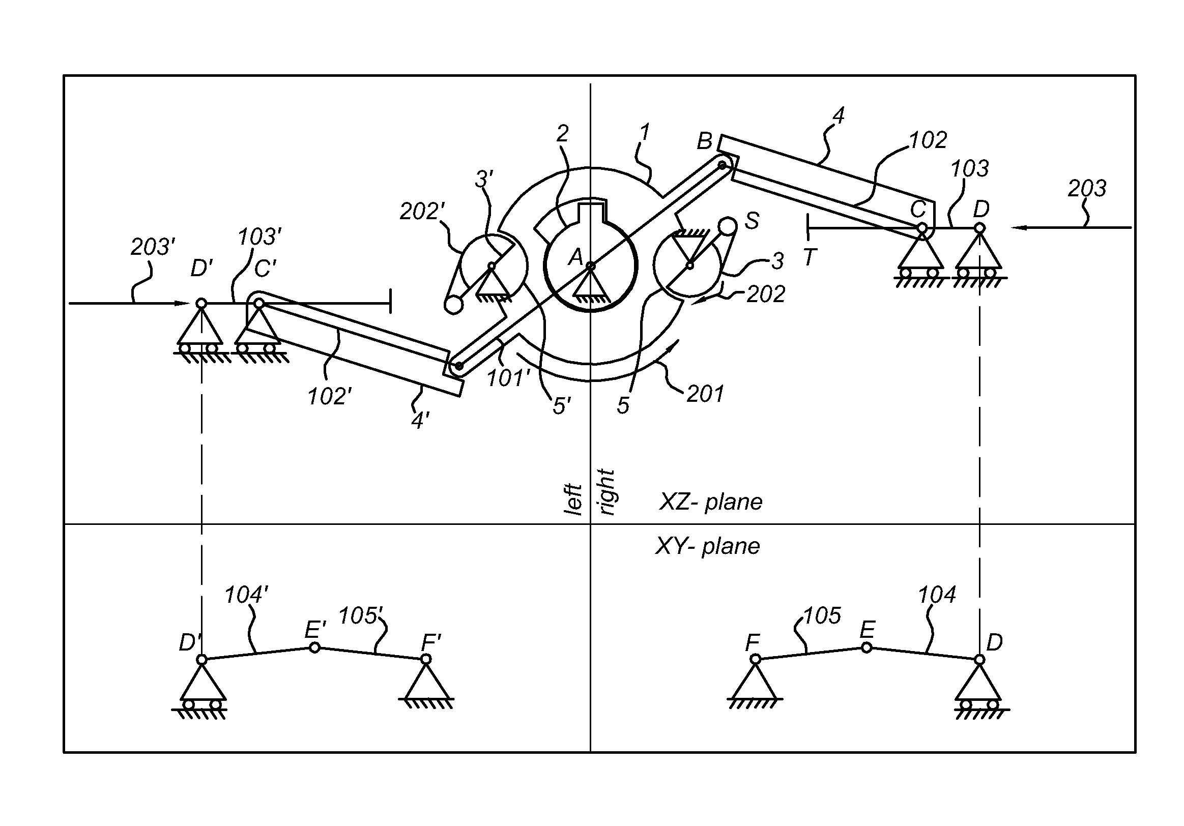
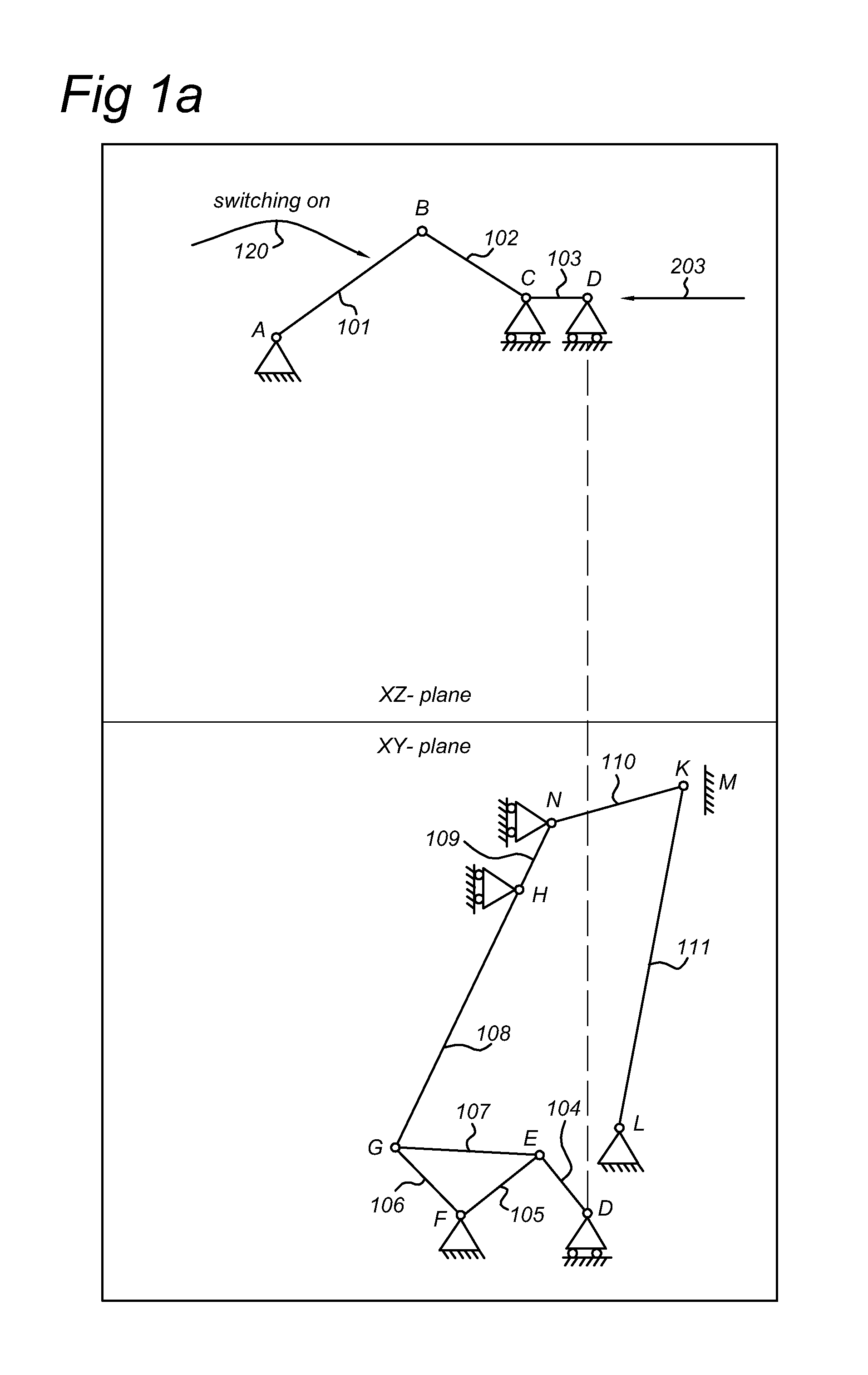
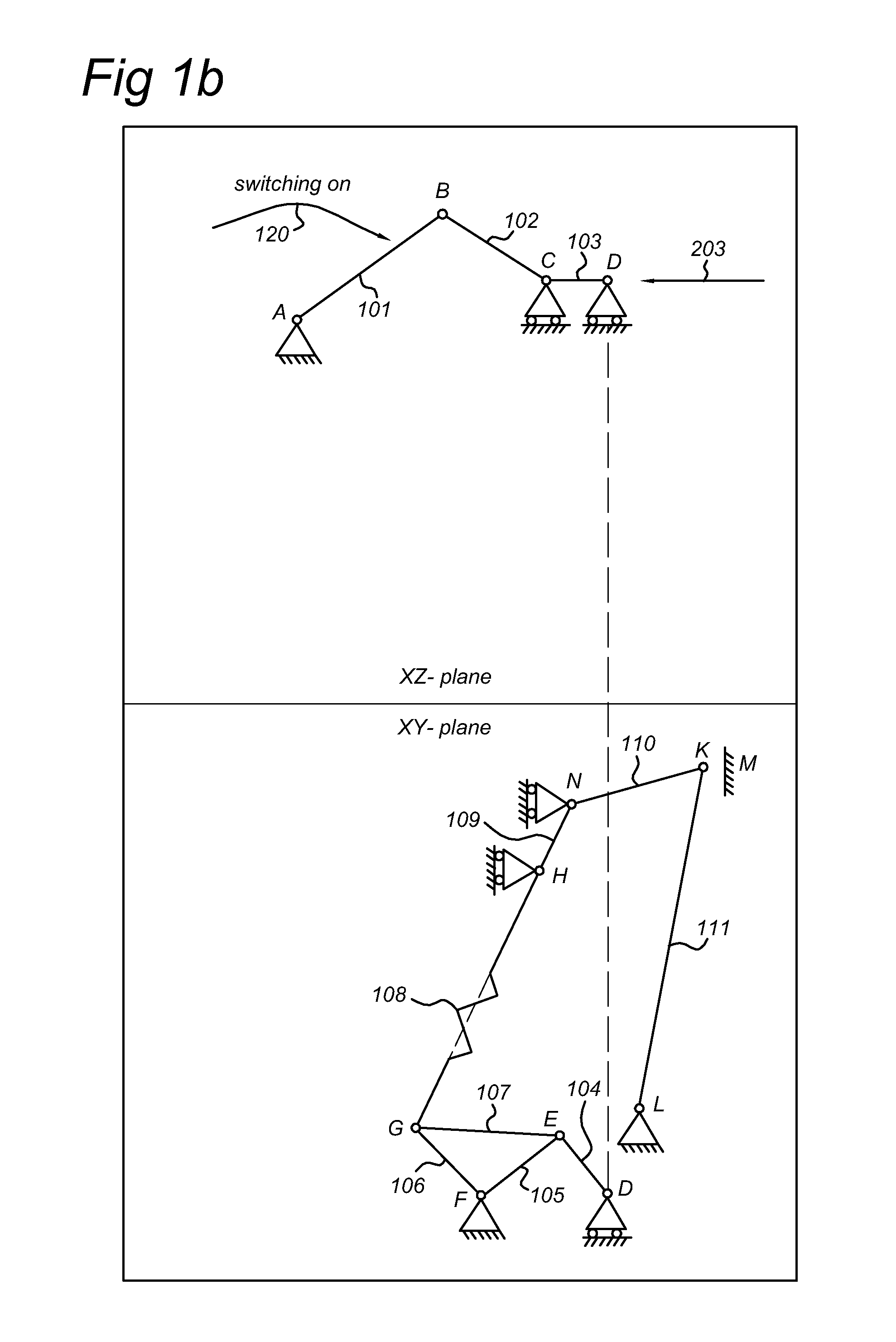
[0033]FIG. 1a is a schematic drawing of the operation mechanism of the switch. A lever 101 rotates around an axis A which is mounted in the switch housing. This lever 101 connects to a second lever 102 through a joint B, and the second lever 102 drives a slider 103. The slider 103 makes a linear movement along the line through a joint C and a pivot point D. The slider connects through the pivot point D to another lever 104, which again drivers another lever 105, which is pivoting in the housing around a shaft point F. In the drawing, the rotation of lever 105 is in a plane perpendicular to the plane in which lever 101 rotates, but these planes can also be in another orientation, e.g., in the same plane. Lever 105 drives a movable contact K via intermediate levers 106, 107, 109, 110, 111, connectors G, H, N, L, and a pretensioned spring 108, e.g., a leaf spring as drawn in FIG. 1b. The movable contact K can thus be moved in contact to or away from the fixed contact M. Although this e...


PUM


Abstract

An electrical switch includes a rotary switch actuator device, and an actuator locking device. The actuator locking device inhibits the rotation of the rotary switch actuator device when the contacts of the switch are closed. Only when the operator tries to open the switch with an operating handle and the contacts do actually open, a lock release device will release the actuator locking device, and allow the operator to move the operator handle to the position corresponding to the open condition. When the contacts do not open, e.g., because they are welded, the actuator locking device will remain locked and the handle movement is blocked. This provides a robust and safe switch that never gives a false “OFF” indication.

Description

[0001]This application claims priority from European Regional patent application No. 07110300.6, filed Jun. 14, 2007, which is hereby incorporated by reference herein.FIELD OF THE INVENTION[0002]The invention relates to a electrical switch comprising a rotary switch actuator device, operated by an operating handle, an actuator locking device, which substantially inhibits the rotary switch actuator device to change position when the actuator locking device is in its locked condition and a switch contact pair comprising a movable contact and a respective opposite contact for mutual contact, the movable contact being connected to the rotary switch actuator device.BACKGROUND INFORMATION[0003]Such a switch is known from US patent application US 2006 / 0278516. The known electrical switch device comprises a body upon which is mounted a hand lever that rotates about a main axis, cooperating with a transmission shaft able to control the opening or the closing of electrical contacts of the ele...

Claims


Application Information

Patent Timeline
Patent Type & Authority Applications(United States)
IPC IPC(8): H01H9/28
CPCH01H9/20H01H9/286H01H2009/288
Inventor POSTMUS, ALBERT JOZEF PETER
Owner EATON ELECTRIC INC
Why Eureka
Try Eureka