Device for processing workpieces using ultrasound and method for operating that device

a technology for workpieces and ultrasound, applied in the direction of metal working devices, etc., can solve the problems of uncontrollable oscillation of the ultrasound tool and also the counter tool, and the short time of the ultrasound tool and the counter tool, so as to prevent uncontrollable oscillation of the counter tool, the effect of reducing oscillation and substantially increasing the quality of the cut or welding

Inactive Publication Date: 2007-11-01
HERRMANN ULTRACHALLTECHNIK GMBH & CO KG
View PDF5 Cites 3 Cited by
  • Summary
  • Abstract
  • Description
  • Claims
  • Application Information

AI Technical Summary

Benefits of technology

[0015]The inventive device offers the substantial advantage that the counter tool is not rigidly held, but exerts a force in the direction of the ultrasound sonotrode which means that the counter tool can give way even when this force is exceeded by the ultrasound sonotrode. When the clearance changes e.g. due to temperature fluctuations, the counter tool either follows or gives way to the ultrasound sonotrode, thereby maintaining high cutting quality and considerably reducing the wear on the working surfaces of the tools.
[0026]The ultrasound sonotrode is thus fed until it contacts the workpiece and additionally also moves the counter tool, thereby pressing onto the workpiece with a predetermined feed force. During this process, the counter tool is moved by a working path. Deflection of the counter tool ensures that the workpiece, which is pressed onto the ultrasound sonotrode via the counter tool, is completely processed, in particular, completely separated. Temperature-related length changes can be neglected in the entire system. The small eigen frequency resulting from mass, spring rate and damping of the counter tool, prevents the working surfaces from being damaged, since the counter tool remains at the outermost apex of the ultrasound tool.

Problems solved by technology

The travel path may also be limited.
These techniques have proven to be problematic in that, when the workpiece has been separated, the ultrasound tool and the counter tool contact each other.
The ultrasound tool and also the counter tool are worn within a very short time due to notches and deformations that are formed in the contact surfaces.
Moreover, only a limited number of materials or degrees of hardness may be used for ultrasound processing, since the materials which can be used for the tools are very limited.
The cutting quality greatly decreases with increasing wear of the tool.
However, fast switching-off of the ultrasound, fast cancellation of the cutting force or fast removal of the ultrasound tool from the counter tool cannot prevent contact.
There are still a relatively large number of contacts due to the high frequency of the ultrasound tools.
Moreover, it has turned out to be difficult to exactly adjust the ultrasound tool relative to the counter tool in order to solve the contact problem, since the position of the components relative to each other is influenced by a plurality of variables.

Method used


Image

  • Device for processing workpieces using ultrasound and method for operating that device
  • Device for processing workpieces using ultrasound and method for operating that device
  • Device for processing workpieces using ultrasound and method for operating that device

Examples


Embodiment Construction

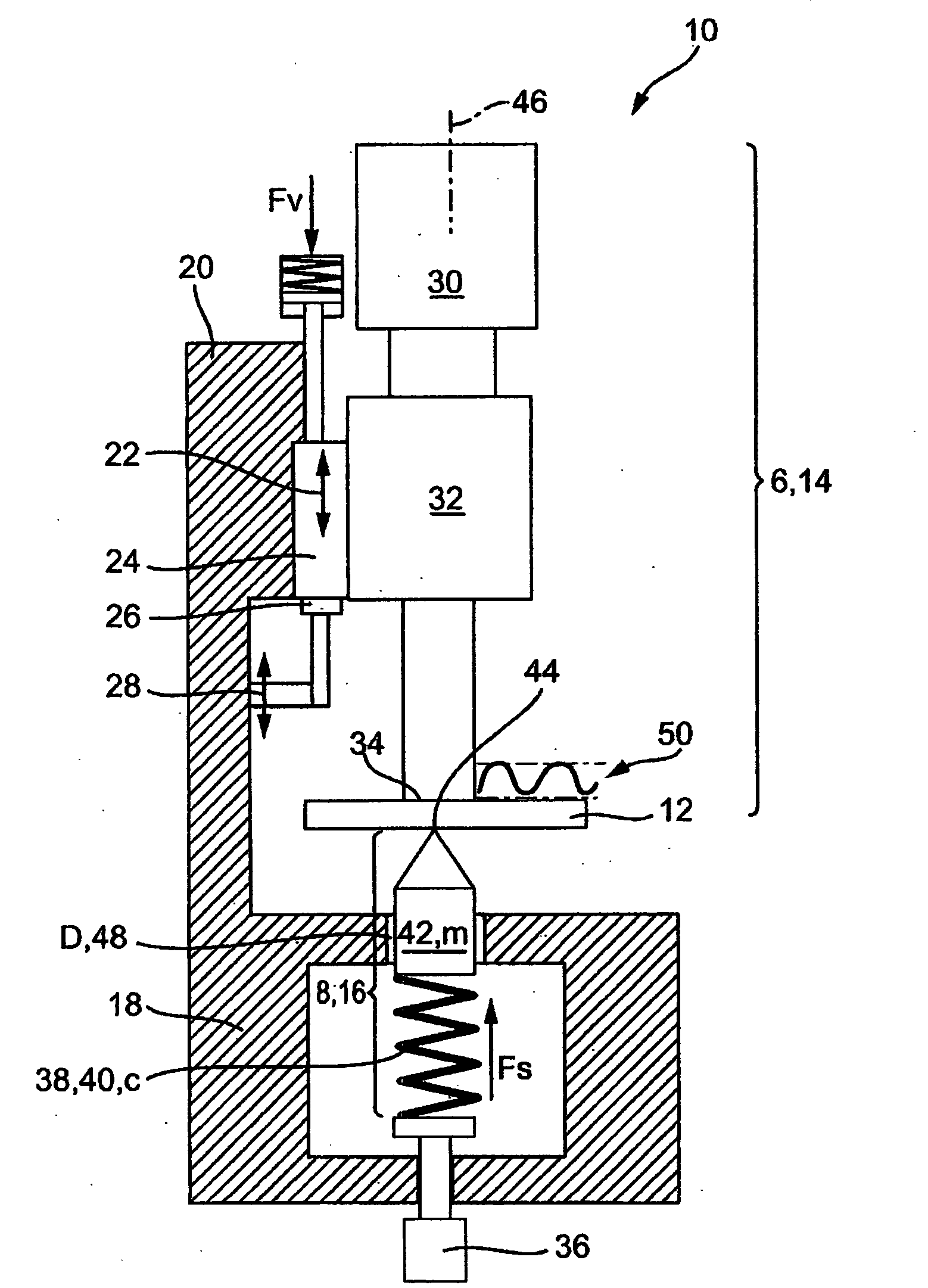
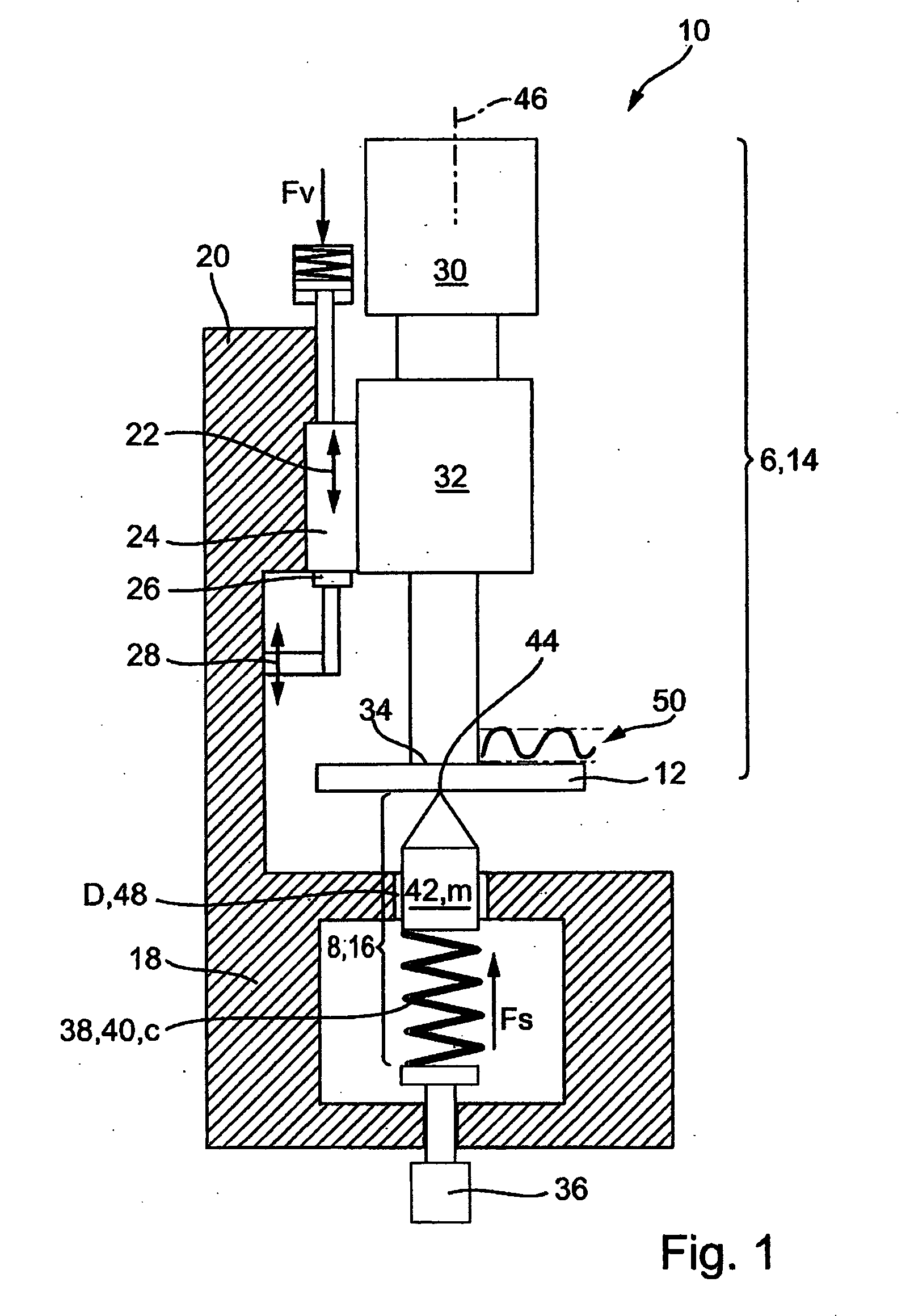
[0032]FIG. 1 shows a device for processing a workpiece 12 using ultrasound, which is designated in total with reference numeral 10. The device 10 consists of a first tool part 6, which is formed in FIG. 1 by an ultrasound oscillating structure 14, and a second tool part 8 which is formed by an anvil 16 which is disposed below the ultrasound oscillating structure 14. The anvil 16 is in a machine frame 18, to the arm 20 of which the ultrasound oscillating structure 14 is mounted by a carriage 24 which can be moved in the direction of the double arrow 22. The figure also shows a fixed stop 26 whose position can be adjusted in the direction of the double arrow 28. The ultrasound oscillating structure 14 has a converter 30 and an ultrasound sonotrode 32 whose working surface 34 is supported on the upper side of the workpiece 12. The anvil 16 is provided with an adjusting device 36 which is disposed in the machine frame 18. A force storage 40 formed by a mechanical spring 38, e.g. a helic...


PUM

PropertyMeasurementUnit
force of travelaaaaaaaaaa
resonance frequencyaaaaaaaaaa

Abstract

A device for processing workpieces using ultrasound, comprises an ultrasound oscillating structure and an anvil with a counter tool, wherein the ultrasound oscillating structure has an ultrasound sonotrode which can be moved by a carriage in the axial direction thereof and in the direction of the counter tool. A force storage is provided for the counter tool to urge the counter tool with a force towards the ultrasound sonotrode. The invention also concerns a method for operating such a device.

Description

[0001]This application claims Paris Convention priority of DE 10 2006 020 429.8 filed Apr. 26, 2006 and DE 10 2006 041 655.4 filed Aug. 24, 2006 the complete disclosures of which are hereby incorporated by reference.BACKGROUND OF THE INVENTION[0002]The invention concerns a device for processing workpieces using ultrasound, comprising a first tool part and a second tool part, wherein the first tool part can be moved by a carriage in the working direction thereof, and towards the second tool part.[0003]Devices for processing workpieces are disclosed in EP-A 1 108 494, EP-A 1 466 709, DE-A 696 21 134, DE-U 295 07 068, DE-A 35 29 686, DE-A 197 16 018, WO-A 96 109 919, EP-A 1 112 823, DE-A 195 81 256, DE-A 44 39 284, WO-A 96 014 202, DE-A 10 2004 013 050, DE-A 10 2004 013 049 and DE-U 202 06 561. Devices of this type are used to process (in particular cut) thermoplastic materials, fabrics, paper and the like. It is thereby desired to reduce the cutting forces and / or optimize the cutting ...

Claims


Application Information

Patent Timeline
Patent Type & Authority Applications(United States)
IPC IPC(8): B26D1/00
CPCB26D7/086B29C66/9513B29C65/7443B29C66/80B29C66/8161B29C66/8242B29C66/8244B29C66/92443B29C66/92651B29C66/929B29C66/9516B29K2995/007B29C65/08B29C66/8322B29C66/81417B29C65/00B29C66/81264B29C66/8223B29C66/8246Y10T83/04Y10T83/8798Y10T83/97
Inventor VOGLER, ULRICH
Owner HERRMANN ULTRACHALLTECHNIK GMBH & CO KG
Why Eureka
Try Eureka