Positioning a coarse actuator of compound actuator tape servo system at midpoint of maximum peaks of lateral tape movement

a technology of compound actuators and actuators, applied in the field of servo systems, can solve the problems of coarse actuator wear, unusable dynamic effects, shorten the life of coarse actuators,

Inactive Publication Date: 2011-11-15
IBM CORP
View PDF15 Cites 12 Cited by
  • Summary
  • Abstract
  • Description
  • Claims
  • Application Information

AI Technical Summary

Benefits of technology

[0008]Methods, servo systems, data storage drives, and computer program products are provided for positioning a head laterally to enable following lateral motion of a longitudinal tape having at least one longitudinal defined servo track. The servo system comprises at least one servo sensor configured to sense lateral position of the head with respect to defined servo tracks, a fine actuator configured to translate the head laterally with respect to the longitudinal tape, a coarse actuator configured to translate the fine actuator laterally with respect to the longitudinal tape, and a position error signal loop configured to sense the servo sensor(s), to determine position error between the head and a desired position related to the defined servo track(s), and to operate the fine actuator to translate the head laterally in a manner to reduce the determined position error.

Problems solved by technology

The flanges of the tape guides, such as rollers, limit the lateral motion of the tape, but may tend to flex the tape and to introduce debris accumulation of the flanges that impact the lifetime of the tape and in addition create undesirable dynamic effects.
This motion tends to wear and shorten the life of the coarse actuator, and is a use of power by the coarse actuator.

Method used


Image

  • Positioning a coarse actuator of compound actuator tape servo system at midpoint of maximum peaks of lateral tape movement
  • Positioning a coarse actuator of compound actuator tape servo system at midpoint of maximum peaks of lateral tape movement
  • Positioning a coarse actuator of compound actuator tape servo system at midpoint of maximum peaks of lateral tape movement

Examples


Embodiment Construction

[0026]This invention is described in preferred embodiments in the following description with reference to the Figures, in which like numbers represent the same or similar elements. While this invention is described in terms of the best mode for achieving this invention's objectives, it will be appreciated by those skilled in the art that variations may be accomplished in view of these teachings without deviating from the spirit or scope of the invention.

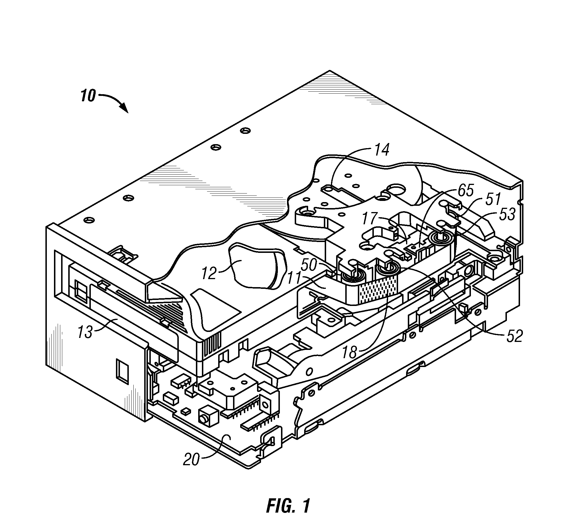
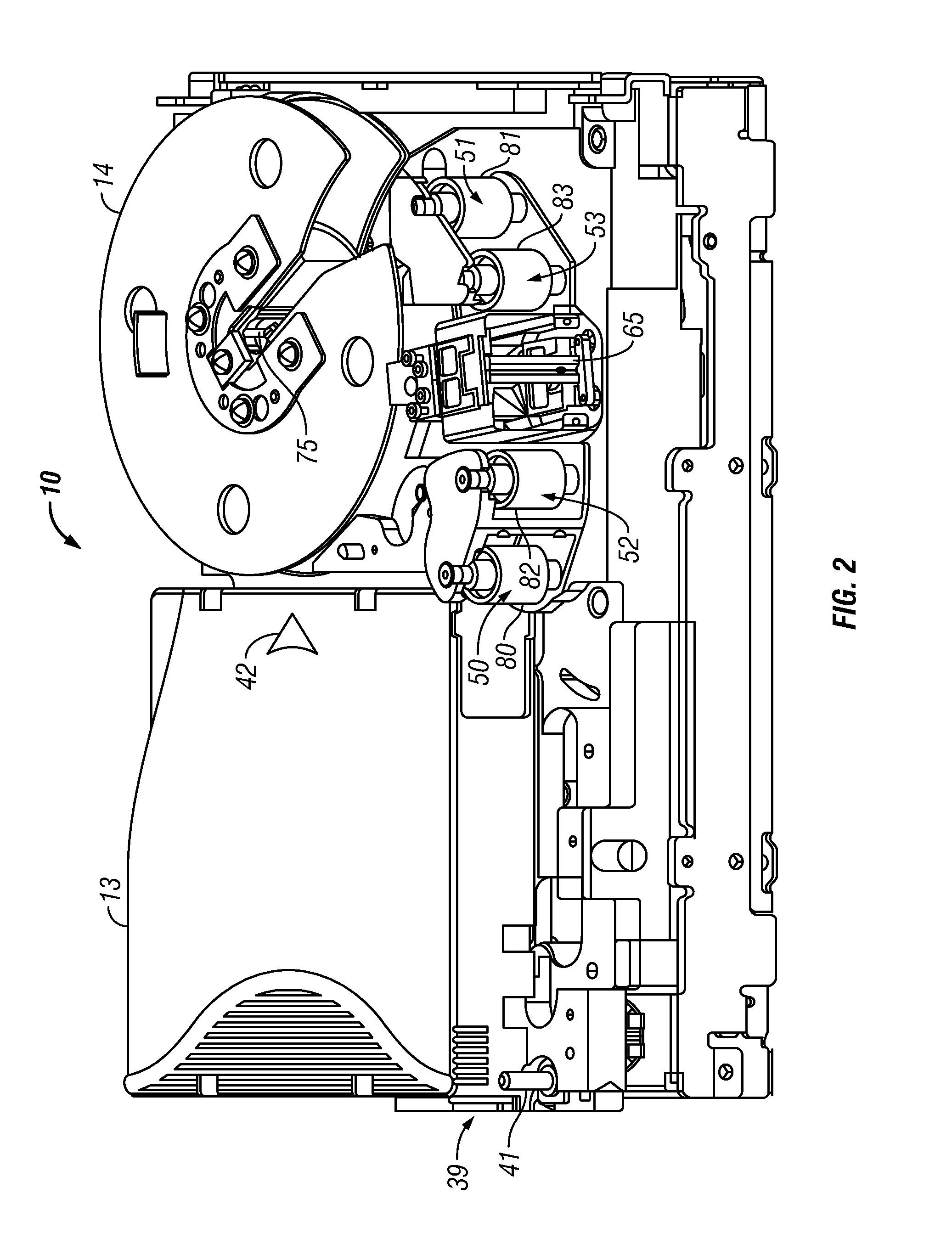
[0027]FIGS. 1 and 2 illustrate a magnetic tape data storage drive 10 which writes data 18 to and reads data from longitudinal tape comprising magnetic tape data storage media 11. As is understood by those of skill in the art, magnetic tape data storage drives, also called magnetic tape drives or tape drives, may take any of various forms. The illustrated magnetic tape drive 10 moves the magnetic tape 11 along a tape path in the longitudinal direction of the tape from a supply reel 12 in a magnetic tape data storage cartridge 13 to a ...


PUM

PropertyMeasurementUnit
thresholdaaaaaaaaaa
magneticaaaaaaaaaa
position error thresholdaaaaaaaaaa

Abstract

Where a tape is subject to lateral shift excursions from one side of a head to another, a coarse actuator is positioned laterally to enable a fine actuator to follow lateral motion of a longitudinal tape having at least one longitudinal defined servo track. A position error signal loop is configured to sense servo sensor(s) and to determine position error between the head and a desired position related to the defined servo track(s). A servo control senses the lateral shift excursion of the defined servo track(s); determines a maximum positive peak and a maximum negative peak of the lateral shift excursion; and positions the coarse actuator substantially at a midpoint of the maximum positive peak and the maximum negative peak of lateral shift excursion of the defined servo track(s). Thus, the fine actuator follows the lateral shift excursion, while the coarse actuator remains at the midpoint.

Description

DOCUMENT INCORPORATED BY REFERENCE[0001]Commonly assigned U.S. patent application Ser. No. 12 / 612,403, Filed Nov. 4, 2009, is incorporated for its showing of a tape servo system for positioning a coarse servo actuator to allow a fine servo actuator to follow tape shift excursions.FIELD OF THE INVENTION[0002]This invention relates to servo systems for longitudinal tape driven in a longitudinal direction, and more particularly to track following servo systems for following longitudinal servo tracks defined on the longitudinal tape as the tape shifts in a lateral direction.BACKGROUND OF THE INVENTION[0003]The function of a track following servo system for longitudinal tape, such as magnetic tape, is to move a head laterally of the longitudinal tape to accurately follow the lateral movement of the tape, for example, during read / write operations of the head. If done accurately, the data tracks are written and read in straight lines along the longitudinal tape as the tape is driven in the...

Claims


Application Information

Patent Timeline
Patent Type & Authority Patents(United States)
IPC IPC(8): G11B5/584
CPCG11B5/584
Inventor HANCOCK, REED ALANINCH, RANDY CLARKJUDD, KEVIN BRUCETSURUTA, KAZUHIRO
Owner IBM CORP
Why Eureka
Try Eureka