Capacitive discharge method for writing to non-volatile memory
What is Al technical title?
Al technical title is built by PatSnap Al team. It summarizes the technical point description of the patent document.
a discharge method and non-volatile memory technology, applied in the field of data storage technology, can solve the problems of difficult operation of memory devices that employ reversible resistance-switching materials
Active Publication Date: 2011-11-15
SANDISK TECH LLC
View PDF29 Cites 17 Cited by
Summary
Abstract
Description
Claims
Application Information
AI Technical Summary
This helps you quickly interpret patents by identifying the three key elements:
Problems solved by technology
Method used
Benefits of technology
Problems solved by technology
However, operating memory devices that employ reversible resistance-switching materials is difficult.
Method used
Image
Click on the blue label to locate the original text in one second.
Reading with bidirectional positioning of images and text.
Examples
Embodiment Construction
[0043]A memory system is provided that includes memory cells with a reversible resistivity-switching element. Various circuits and methods are disclosed for controlling the setting and resetting of the resistance for the reversible resistance-switching elements.
Memory Cell and System
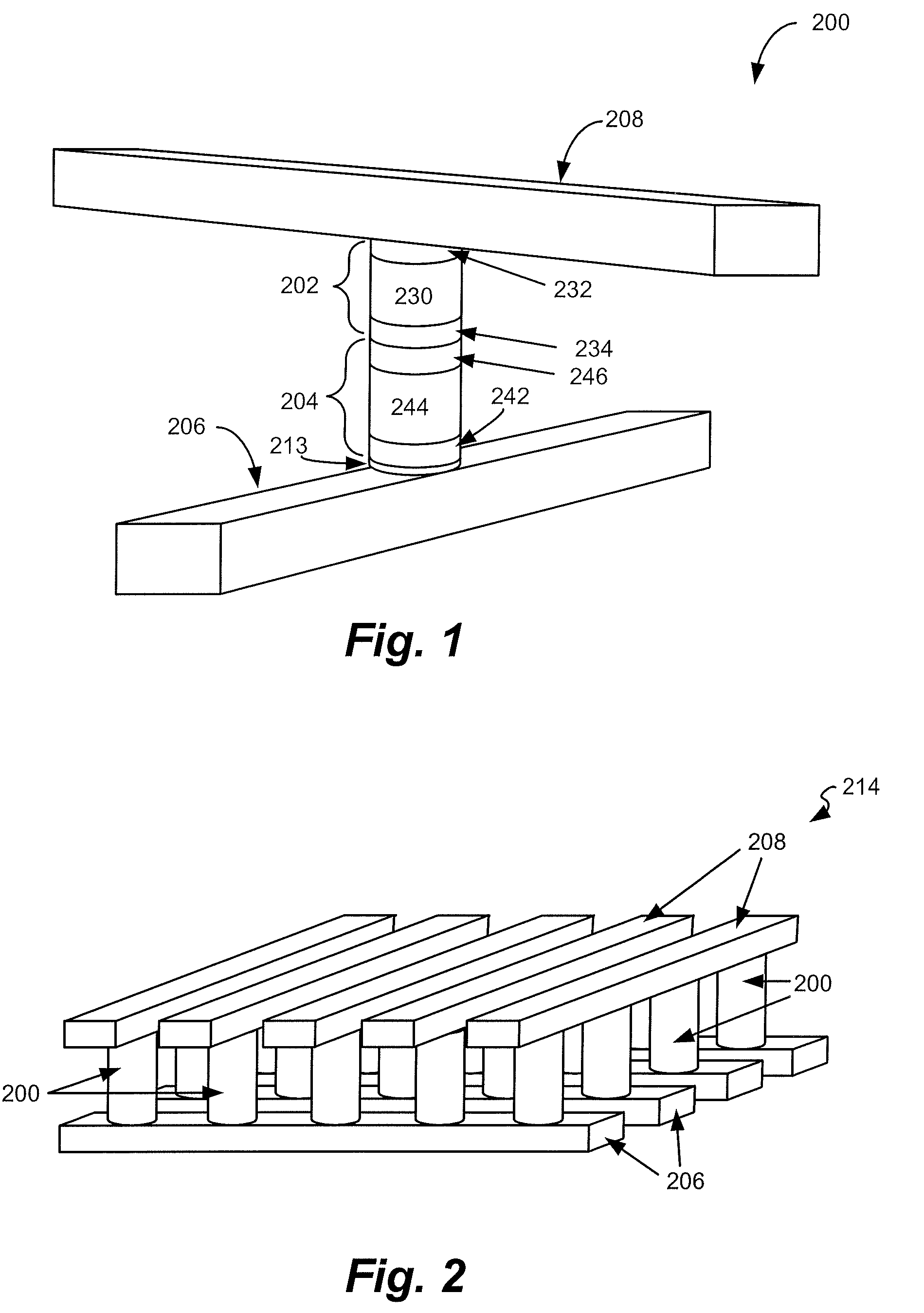
[0044]FIG. 1 is a simplified perspective view of one embodiment of a memory cell 200 which includes a reversible resistance-switching element 202 coupled in series with a steering element 204 between a first conductor 206 and a second conductor 208.
[0045]Reversible resistance-switching element 202 includes reversible resistivity-switching material 230 having a resistivity that may be reversibly switched between two or more states. For example, the reversible resistivity-switching material may be in an initial high-resistivity state upon fabrication that is switchable to a low-resistivity state upon application of a first voltage and / or current. Application of a second voltage and / or current may return th...
PUM
Abstract
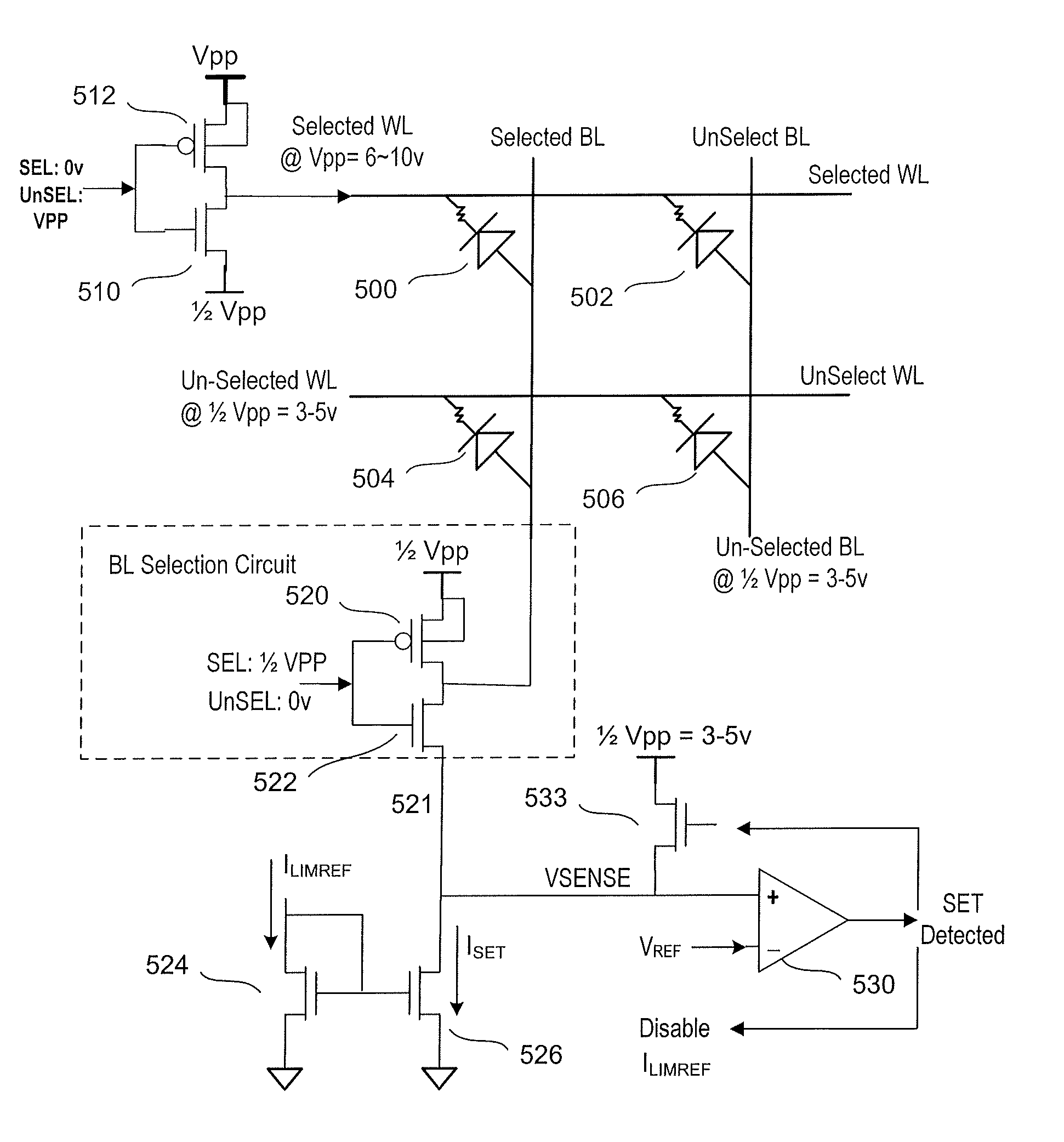
A memory system includes a substrate, control circuitry on the substrate, a three dimensional memory array (above the substrate) that includes a plurality of memory cells with reversible resistance-switching elements, and circuits for limiting the SET current for the reversible resistance-switching elements. The circuits for limiting the SET current provide a charge on one or more bit lines that is not sufficient to SET the memory cells, and then discharge the bit lines through the memory cells in order to SET the memory cells.
Description
[0001]This application claims priority from provisional application 61 / 076,553, filed on Jun. 27, 2008.BACKGROUND[0002]1. Field[0003]The present invention relates to technology for data storage.[0004]2. Description of the Related Art[0005]A variety of materials show reversible resistance-switching behavior. These materials include chalcogenides, carbon polymers, perovskites, and certain metal oxides and nitrides. Specifically, there are metal oxides and nitrides which include only one metal and exhibit reliable resistance switching behavior. This group includes, for example, NiO, Nb2O5, TiO2, HfO2, Al2O3, MgOx, CrO2, VO, BN, and AlN, as described by Pagnia and Sotnick in “Bistable Switching in Electroformed Metal-Insulator-Metal Device,” Phys. Stat. Sol. (A) 108, 11-65 (1988). A layer of one of these materials may be formed in an initial state, for example a relatively low-resistance state. Upon application of sufficient voltage, the material switches to a stable high-resistance sta...
Claims
Application Information
Patent Timeline
Application Date:The date an application was filed.
Publication Date:The date a patent or application was officially published.
First Publication Date:The earliest publication date of a patent with the same application number.
Issue Date:Publication date of the patent grant document.
PCT Entry Date:The Entry date of PCT National Phase.
Estimated Expiry Date:The statutory expiry date of a patent right according to the Patent Law, and it is the longest term of protection that the patent right can achieve without the termination of the patent right due to other reasons(Term extension factor has been taken into account ).
Invalid Date:Actual expiry date is based on effective date or publication date of legal transaction data of invalid patent.
