Sound dampening flow channel device

a flow channel and sound dampening technology, which is applied in the direction of sound producing devices, pipe elements, building components, etc., can solve the problems of unwanted effects, pressure drop, and reduced volume flow, and achieve the effect of effective sound dampening and minimising the pressure drop of fluid flow

Active Publication Date: 2011-11-22
TUMANE ENTERPRISES
View PDF45 Cites 19 Cited by
  • Summary
  • Abstract
  • Description
  • Claims
  • Application Information

AI Technical Summary

Benefits of technology

[0010]An object of the invention is to provide a sound dampening flow channel device that allows an effective sound dampening while minimising the pressure drop of a fluid flow through the device.
[0011]Another object is to provide a sound dampening flow channel device that allows an effective sound dampening while minimising the pressure drop of a fluid flow through the device, whereby the dimensions of the device are kept low.
[0012]Another object is to provide a sound dampening flow channel device that allows an effective sound dampening while minimising the pressure drop of a fluid flow through the device, whereby a reduction of the flow cross-section is avoided or minimized.
[0017]Preferably, the acoustic energy dissipative wall presents, in relation to the interior of the flow channel, a smooth curvature. The smooth curvature will prevent Separation of the fluid flow from the wall, which prevention will further reduce the pressure drop.
[0032]Instead of being provided with a dampening layer, at least one of the acoustic energy dissipative walls could be made of a material having an inherently high vibration loss factor, such as plastic materials, in particular EVA, acrylics or silicone. Such a wall could be provided microperforations. The latter have, besides providing absorption by acoustic resistance, the effect of increasing the vibration loss factor of the wall.

Problems solved by technology

However, this will inevitably cause unwanted effects like a pressure drop, noise generated by turbulence, and reduced volume flow.
However, a disadvantage with such a solution is that it requires space outside the stream flow duct, and such space can be limited or non-existing in many applications.
A disadvantage with this solution is that the volume behind the linings or the baffles does not participate as a flow duct, but rather reduces the flow cross-section area.
However, due to the angle of the vanes, and the large thicknesses of the vanes and the absorption layers, the vanes will cause a reduction of the flow cross-section.
Further, the bending of the flow to a zigzag shape will cause a pressure drop.

Method used


Image

  • Sound dampening flow channel device
  • Sound dampening flow channel device
  • Sound dampening flow channel device

Examples


Embodiment Construction

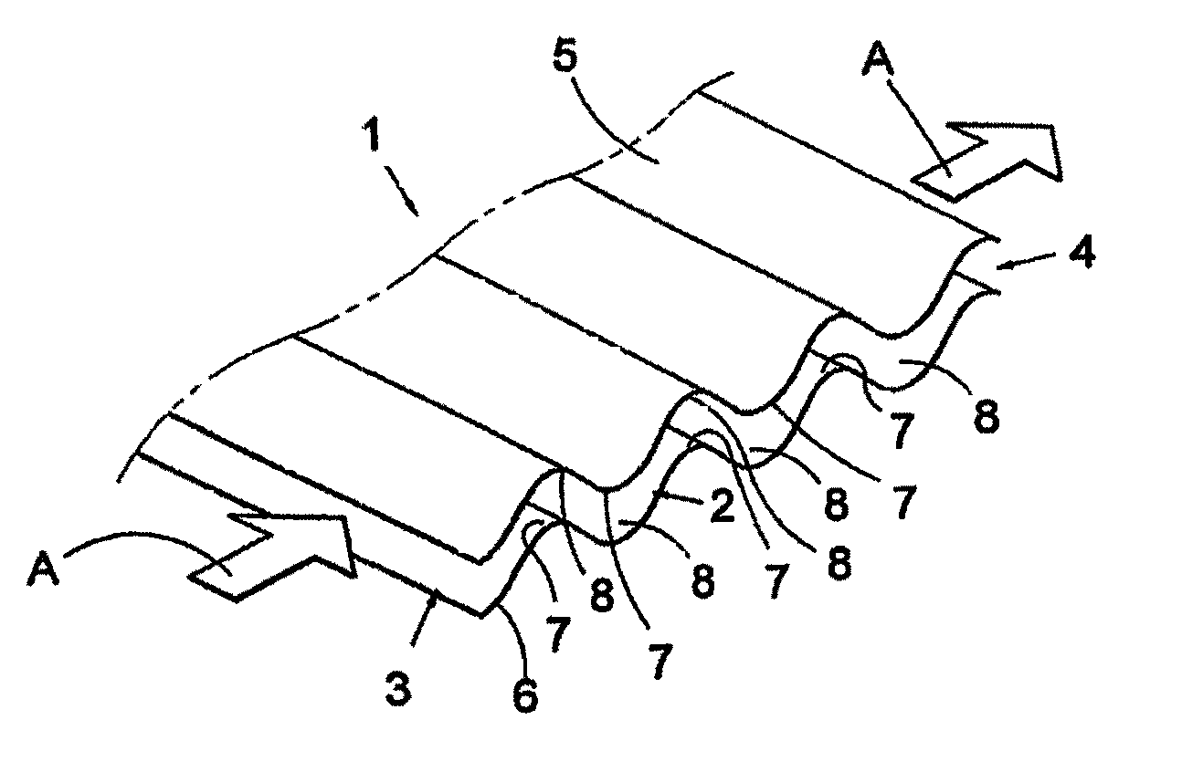
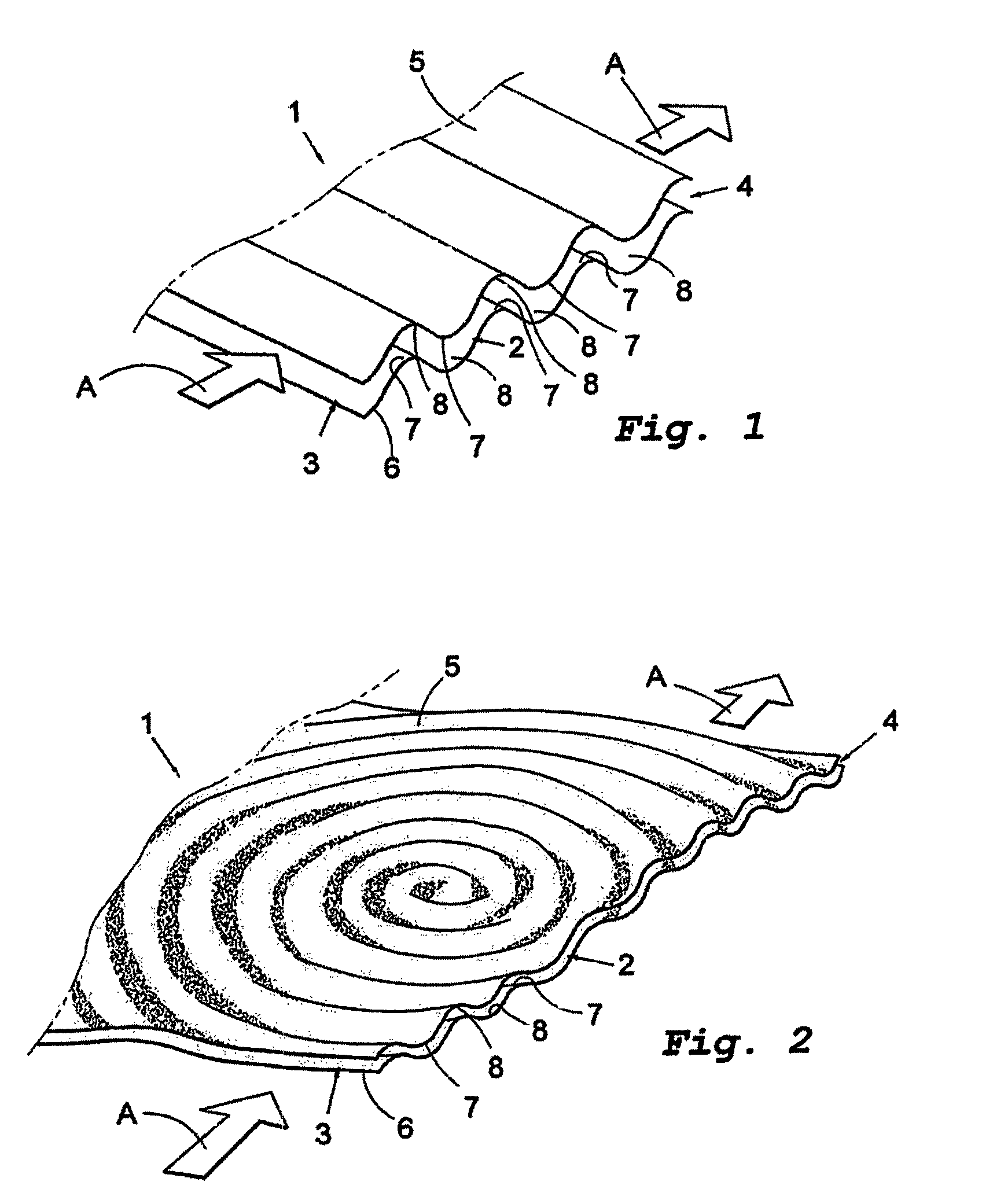
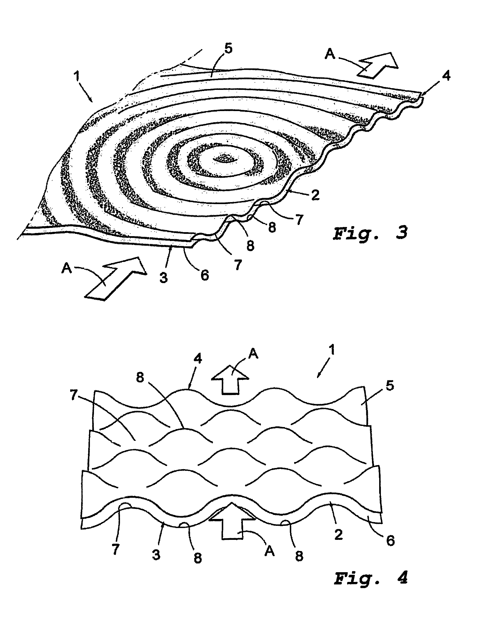
[0053]FIG. 1 shows a perspective cross-sectional view of a part of a sound dampening flow channel device 1 according to one embodiment of the invention. The device 1 defines a flow channel 2 having an inlet opening 3 and an outlet opening 4. The direction of a fluid flow is indicated with arrows A. The flow channel 2 is partly delimited by two acoustic energy dissipative walls 5, 6. The flow channel can further be delimited by two walls not shown in FIG. 1, oriented perpendicular to the acoustic energy dissipative walls 5, 6.

[0054]The two acoustic energy dissipative walls 5, 6 are formed by a first sheet 5 and a second sheet 6 defining between them the flow channel 2. The first and second sheets 5, 6 are each provided with a plurality of protrusions 7 and indentations 8. The protrusions 7 and indentations 8 are arranged such that the outlet opening 4 of the flow channel 2 can not be seen from the inlet opening 3 and vice versa.

[0055]Each protrusion 7 forms a ridge 7 and each indenta...


PUM


Abstract

The invention presents a sound dampening flow channel device defining at least one flow channel having an inlet opening and an outlet opening, the flow channel being at least partly delimited by at least one acoustic energy dissipative wall. The outlet opening of the flow channel cannot be seen from the inlet opening and vice versa. Preferably, the acoustic energy dissipative wall presents, in relation to the interior of the flow channel, a smooth curvature.

Description

CROSS REFERENCE TO RELATED APPLICATIONS[0001]This application is the National Stage of International Application No. PCT / SE2006 / 050031 filed Mar. 15, 2006, and claims benefit of Swedish Application No. 0500630-9 filed Mar. 18, 2005.TECHNICAL FIELD[0002]The present invention relates to a sound dampening flow channel device defining at least one flow channel.BACKGROUND OF THE INVENTION[0003]Traditionally, sound attenuators or mufflers are used to reduce unwanted sounds in ducts with flowing air. Such a sound attenuator or muffler is usually designed as an add-on component, inserted somewhere along the duct. Among sound attenuators, there are resistive and reactive types.[0004]A purely reactive type reduces the sound only by means of a difference regarding the geometrical dimension in relation to the duct, and can be regarded as a reflector and not an energy dissipative silencer.[0005]A resistive silencer often contains resistive materials like pressed glass or mineral fibre wools, pla...

Claims


Application Information

Patent Timeline
Patent Type & Authority Patents(United States)
IPC IPC(8): F01N1/08
CPCF01N1/083F01N1/086G10K11/161F16L55/033F01N1/12G10K11/162G10K11/172F01N1/04F16L55/02
Inventor CORIN, RALF
Owner TUMANE ENTERPRISES
Why Eureka
Try Eureka