Material-flow control for collision avoidance in a conveyor system
What is AI technical title?
AI technical title is built by Patsnap AI team. It summarizes the technical point description of the patent document.
a conveyor system and material flow technology, applied in the field of conveyor systems, can solve the problems of recognizing the control computer prematurely whether two or more transport units are needed, and achieve the effects of less maintenance, less noise, and power efficien
Active Publication Date: 2011-11-22
SSI SCHAEFER PEEM
View PDF37 Cites 48 Cited by
Summary
Abstract
Description
Claims
Application Information
AI Technical Summary
This helps you quickly interpret patents by identifying the three key elements:
Problems solved by technology
Method used
Benefits of technology
Benefits of technology
[0008]Therefore, it is an object of the present invention to provide a conveyor system as well as a method for conveying transport units being power efficient, free of maintenance and more quiet. Particularly, the throughput of transport units at an intersection point is to be increased, i.e. more transport units per unit of time should be allowed to pass the intersection point.
Problems solved by technology
This means that, for example, a control computer prematurely recognizes whether two or more transport units will meet each other at the crossing or the intersection point, particularly if they will collide with each other.
Method used
Image
Click on the blue label to locate the original text in one second.
Reading with bidirectional positioning of images and text.
Examples
Embodiment Construction
[0043]In the following description of the drawings identical elements will be designated by the same reference numerals. If features are formed differently in comparison to a preceding explanation, this will be explicitly explained.
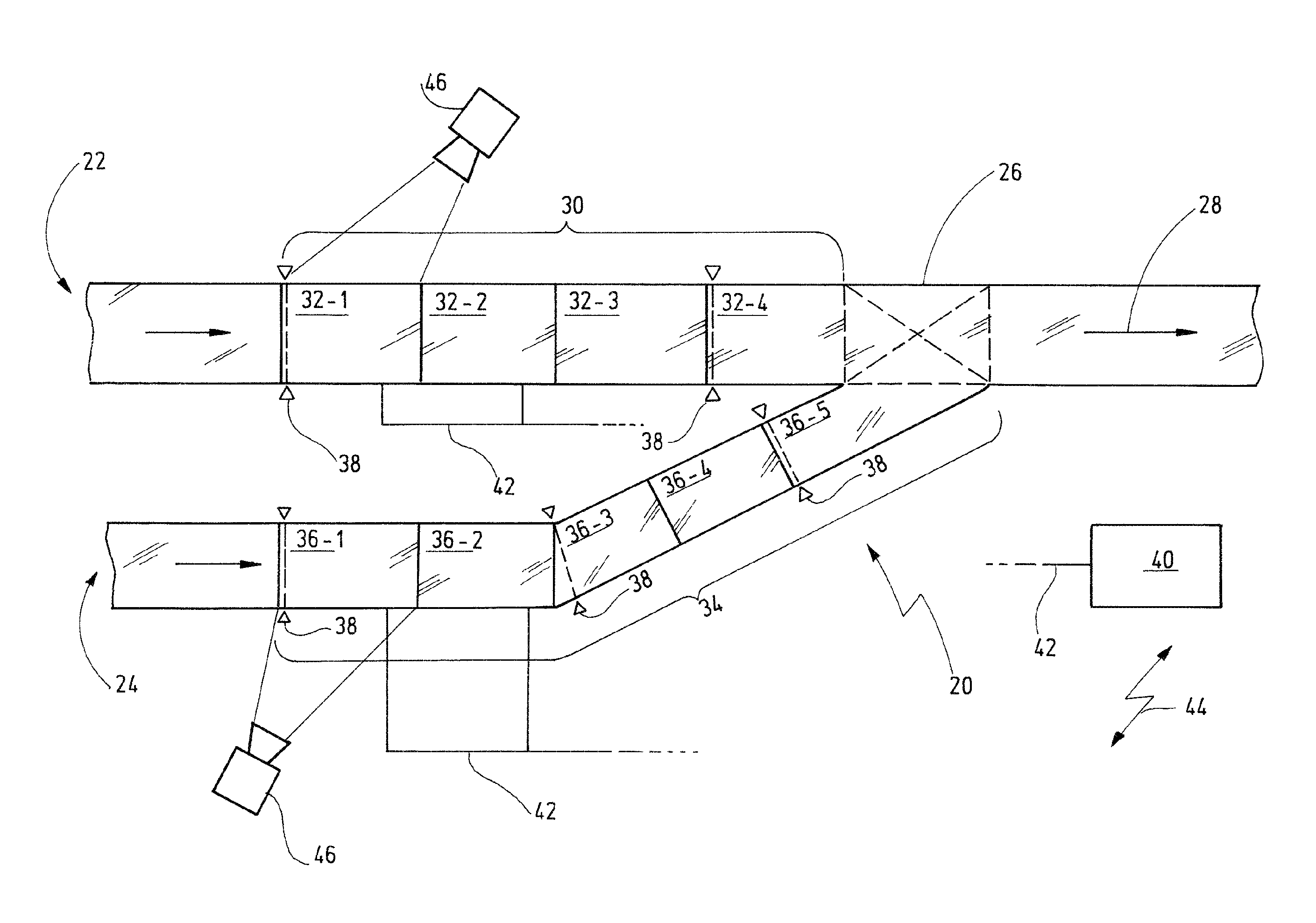
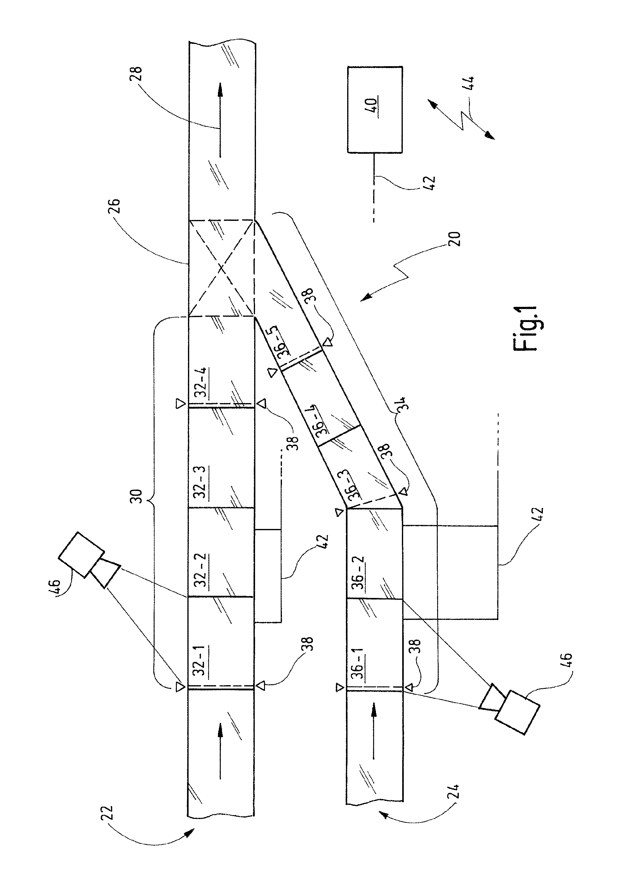
[0044]The present invention relates to an order-picking system 20 as exemplarily depicted in a top view of FIG. 1.
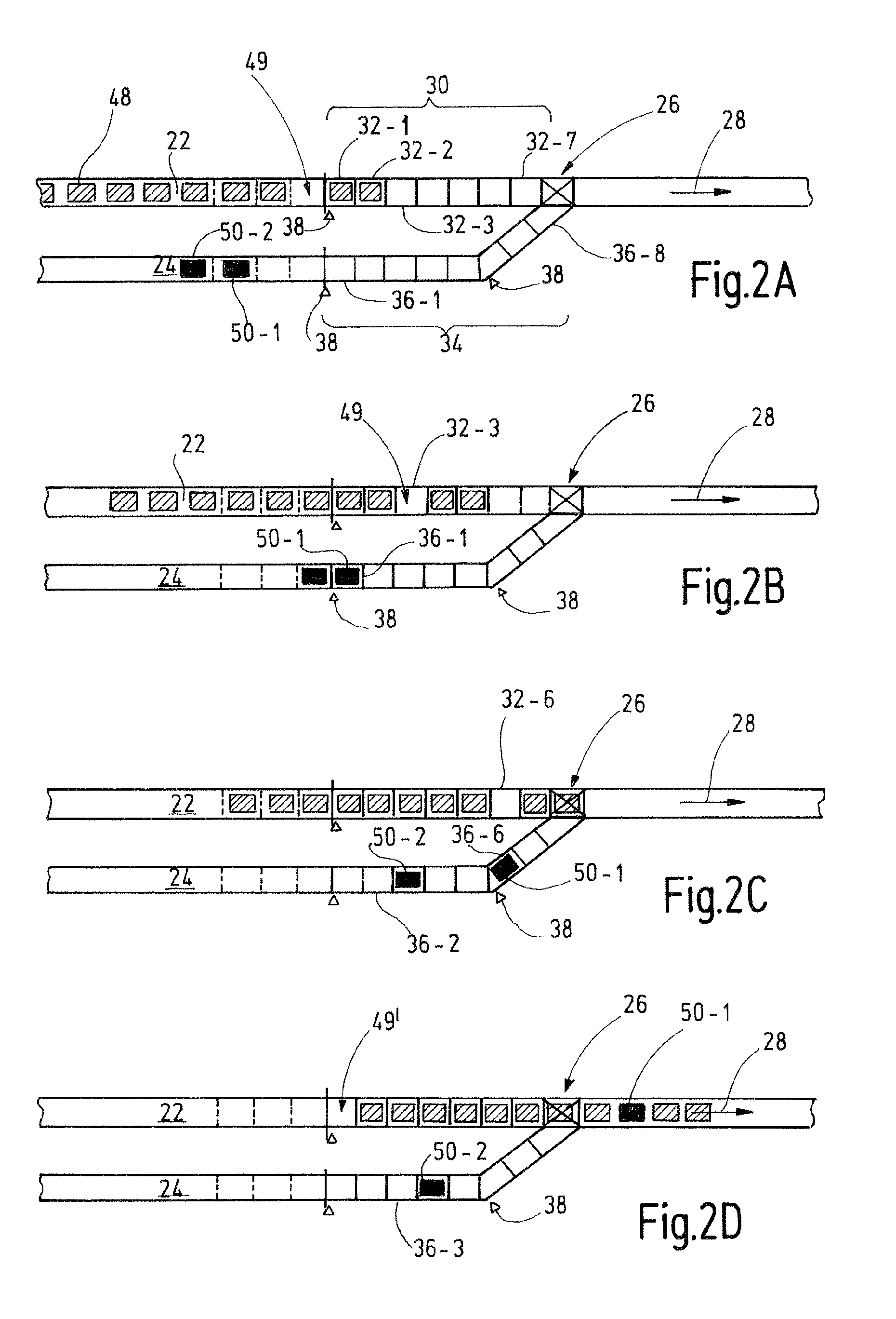
[0045]The present invention particularly can be used with order-picking warehouses. In order-picking warehouses goods, articles, piece goods etc. are often loaded on load supports (trays, pallets, containers, etc.) for allowing conveyance and transportation in the order-picking system. However, the articles can also be transported without load supports. In the following, a transport unit is to be understood either as a combination of an article or goods and a load support, or as an article without a load support. Typically, packing units are handled in terms of articles. For example, one layer of twelve milk bags can be regarded as one article...
PUM
Abstract
The present invention relates to a conveyor system and a method for merging or crossing of at least two conveyor lines (22, 24, 58) on which transport units (48, 50), particularly containers, are conveyed in an upstream direction (28), wherein the conveyor lines (22, 24) meet each other in an intersection point (26), wherein each of the conveyor lines (22, 24, 58) respectively comprises, upstream relative to the intersection point (26), one group (30, 34) of conveyor-line segments (32, 34), wherein the conveyor-line segments are respectively operable with a variable conveying velocity, the method comprising the following steps: conveying transport units (48, 50) towards the intersection point (26); detecting and determining a traffic density of the transport units (48, 50) on the conveyor lines (22, 24, 58), particularly at the conveyor-line segments (32-1, 34-1) which are located upstream; determining conveying velocities for the conveyor-line segments (32, 34) so that transport units (48, 50) which are conveyed on one of the conveyor lines (22, 24) do not collide at the intersection point (26) with other transport units (48, 50) which are conveyed on the other conveyor lines (24, 22), and without the need to stop the transport units (48, 50) in a region of the conveyor-line segments (32, 34); adapting the conveying velocities of the conveyor-line segments (32, 34) to the conveying velocities determined in this way, wherein the conveyor-line segments (32, 34) respectively can be operated at a different conveying velocity.
Description
RELATED APPLICATIONS[0001]This is a continuation application of the co-pending international application PCT / EP2008 / 006727 (WO 2009 / 024298 A1) filed on 15 Aug. 2008 which claims priority of the German patent application DE 10 2007 040 367.6 filed on 17 Aug. 2007, which is fully incorporated herewith by reference.BACKGROUND OF THE INVENTION[0002]The present invention relates to a conveyor system as well as a method for avoiding collisions between transport units, or conveyed goods, at intersection points of conveyor lines, for example, if they cross each other in the intersection point or converge to a single conveyor line.[0003]Conveyor-line switches and crossings are known in the prior art, where the conveyed goods are stopped, if a collision with conveyed goods of another conveyor line is approaching. Typically, the stop of the conveyed goods is conducted by an abrupt deceleration. Then, the conveyed goods are accelerated again as soon as the other conveyed goods have passed the i...
Claims
Application Information
Patent Timeline
Application Date:The date an application was filed.
Publication Date:The date a patent or application was officially published.
First Publication Date:The earliest publication date of a patent with the same application number.
Issue Date:Publication date of the patent grant document.
PCT Entry Date:The Entry date of PCT National Phase.
Estimated Expiry Date:The statutory expiry date of a patent right according to the Patent Law, and it is the longest term of protection that the patent right can achieve without the termination of the patent right due to other reasons(Term extension factor has been taken into account ).
Invalid Date:Actual expiry date is based on effective date or publication date of legal transaction data of invalid patent.

