Intraocular lens injector and method

a technology of intraocular lens and injector, which is applied in the field of intraocular lens (“ iol”) injectors, can solve the problems of optic iols likely damaging dual optic aiols, injectors and rendering useless, and delicate iols likely damaging them

Inactive Publication Date: 2011-11-22
BAUSCH & LOMB INC
View PDF13 Cites 9 Cited by
  • Summary
  • Abstract
  • Description
  • Claims
  • Application Information

AI Technical Summary

Benefits of technology

In one embodiment, the present invention provides an injector for delivering a dual optic AIOL into an eye. The injector includes a main body having a lumen extending between proximal and distal ends. A tip is provided at the distal end and includes a lumen terminating at an opening wherethrough the AIOL is expressed from the injector and into an eye. A plunger is inserted into the proximal end of the main body and telescopes within the lumen in the manner of a syringe. The AIOL is loaded into the lumen in an initially loaded condition wherein the first and second optics are generally in coaxial alignment. An optic displacing element is provided and operable to move the first optic toward the proximal end of the main body whereupon the first optic becomes located proximally of the second optic. A stop may be provided to prevent the second optic from moving proximally with the first optic. Displacing the optics to a non-coaxial condition reduces the cross-sectional area of the AIOL which allows the AIOL to non-destructively compress to the size of the opening of the injector tip which may be as small as about 2.8 mm or less, for example.
The method may further include the step of providing an injector tip having a lumen wherethrough said intraocular lens may travel and be expressed from said injector tip; providing a lens moving element on said injector tip, and attaching said injector tip to said lens mounting surface and thereby causing said lens moving element to move said first optic toward said injector body proximal end.

Problems solved by technology

Absent such control, the delicate IOL would likely be damaged during delivery through the injector and rendered useless.
Thus, injectors designed for single optic IOLs would probably damage a dual optic AIOL since such an injector would not have precise control over the optic / plunger interface.
The number of parts required for the Tsai and Ayton et al injectors greatly increases the complexity of manufacture and assembly of the injector which adds to the cost thereof.
The more injector manipulations required, the more time needed for the IOL implantation procedure which decreases the efficiency of the procedure.

Method used


Image

  • Intraocular lens injector and method
  • Intraocular lens injector and method
  • Intraocular lens injector and method

Examples


Embodiment Construction

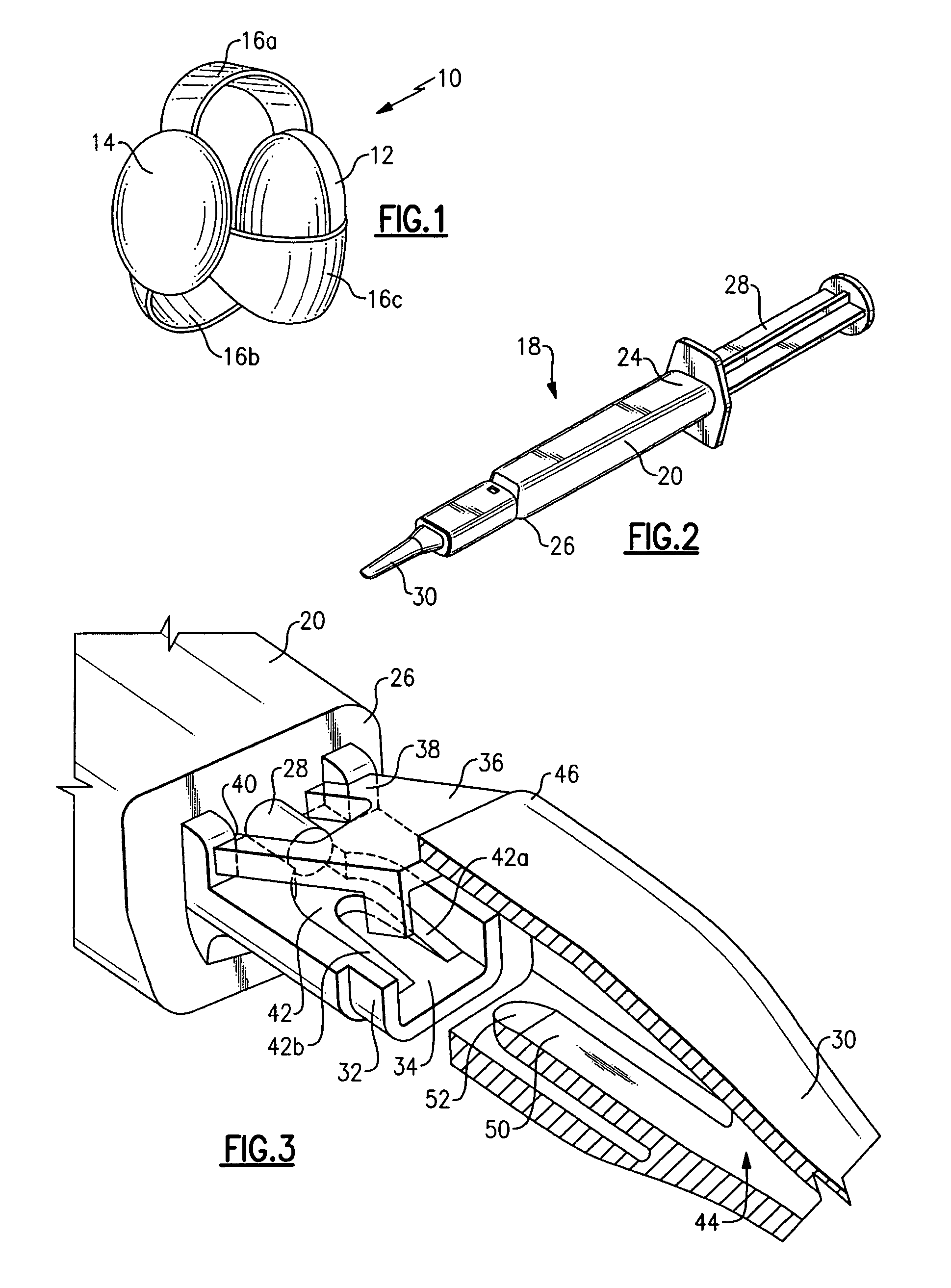
A prior art AIOL 10 is shown in FIG. 1 and includes first and second optics 12, 14, respectively, interconnected by three flexible haptics 16a, b and c. As is well known in the intraocular lens art, AIOL 10 may be made of a hydrophilic or hydrophobic material which may be folded and compressed to deliver the AIOL through the small tip opening of the injector as explained below.

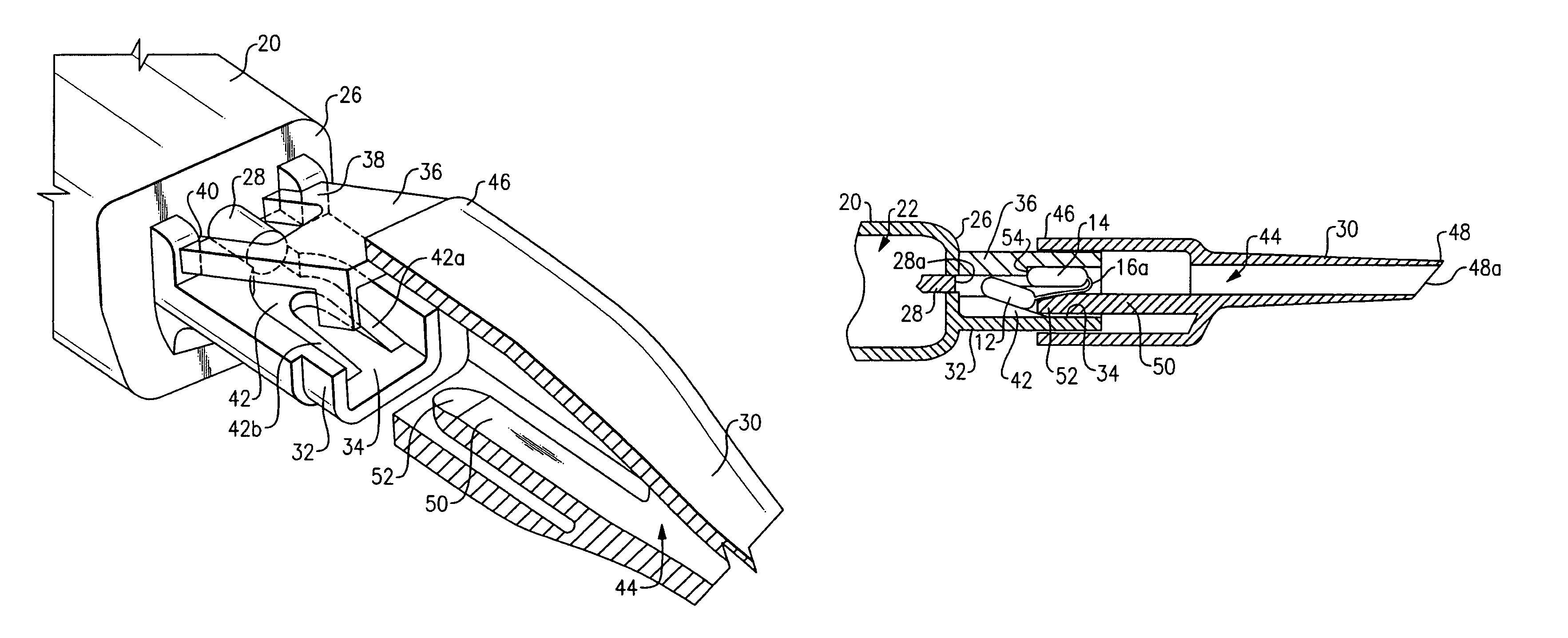
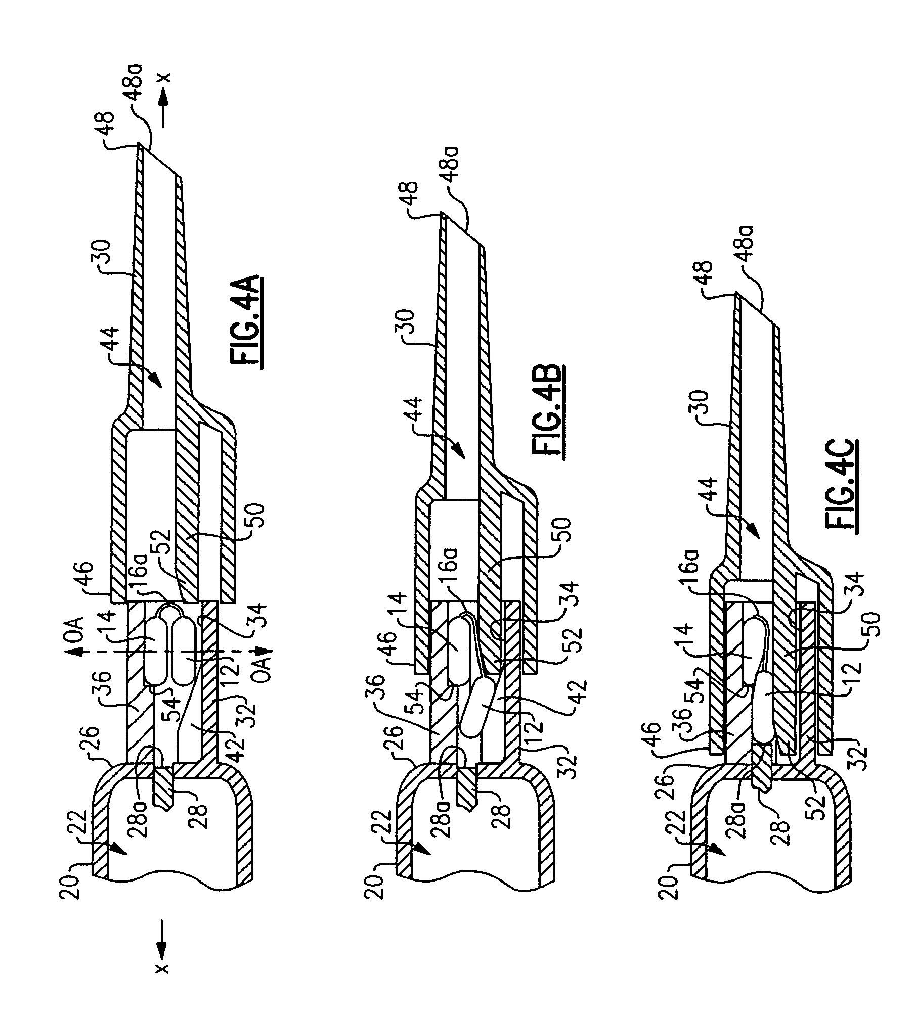
An injector 18 according to an embodiment of the invention is seen in FIG. 2 to include main body portion 20 having a lumen 22 (see FIGS. 4A-C) extending between proximal and distal ends 24, 26 thereof, respectively. A plunger 28 is received in lumen 22 at proximal end 24 of main body portion 20 and operates in the manner of a syringe to express the AIOL 10 from injector tip 30 and into an eye.

Referring to FIG. 3, an embodiment of the invention is seen to include a lens platform 32 extending from main body portion distal end 26. Lens platform 32 includes a lens mounting surface 34 adapted for placing the AIOL ...


PUM


Abstract

An injector and method for injecting a dual optic AIOL into an eye wherein the AIOL is loaded into the injector in an initially loaded condition with the first and second optics in generally coaxial alignment. A lens moving element is provided and operable to move the first optic toward the proximal end of the main body whereupon the first optic becomes located proximally of the second optic. A stop may be provided to prevent the second optic from moving proximally with the first optic. Displacing the optics to a non-coaxial position reduces the cross-sectional area of the AIOL which allows the AIOL to non-destructively compress to the size of the opening of the injector tip which may be as small as about 2.8 mm or less, for example.

Description

BACKGROUND OF THE INVENTIONThe present invention generally relates to intraocular lens (“IOL”) injectors, and more particularly relates to an injector and method for facilitating injection of an accommodating intraocular lens (hereinafter “AIOL”) having two lenses into an eye.AIOLs having two optics interconnected by one or more flexible haptics are known, an example of which may be seen in FIG. 1 hereof. While dual optic AIOLs are relatively new, single optic IOLs have been around for decades. Most of the IOL injector art has therefore been developed around the single optic IOL. A common injector design for delivering a single optic IOL into an eye includes a main body having a lumen extending between distal and proximal ends of the main body. A plunger is received at the proximal end of the body and telescopes within the lumen in the manner of a syringe. A tip is provided at the distal end of the injector body and gradually tapers to an opening wherethrough the IOL is expressed fr...

Claims


Application Information

Patent Timeline
Patent Type & Authority Patents(United States)
IPC IPC(8): A61F2/16
CPCA61F2/1662A61F2/1678A61F2/1648
Inventor POLLOCK, DAVID P.
Owner BAUSCH & LOMB INC
Why Eureka
Try Eureka