Reciprocated pump system for use in oil wells

a technology of reciprocating pump and oil well, which is applied in the direction of positive displacement liquid engine, borehole/well accessories, liquid fuel engine, etc., can solve the problem that the walking beam pumping system cannot run at a slow enough rate, and achieve the effect of reducing the rate of fluid flow, efficient and effective movement of formation fluid, and more efficient actuation of the bottom hole pump

Active Publication Date: 2011-11-29
HENRY RES & DEV +1
View PDF25 Cites 40 Cited by
  • Summary
  • Abstract
  • Description
  • Claims
  • Application Information

AI Technical Summary

Benefits of technology

[0018]Another important advantage of the present invention is the provision of a unique system for adjusting the length of the sucker rod string for more efficient actuation of the bottom hole pump.
[0019]Another aspect of the present invention is an improved reciprocated pump positioned at the lower end of a string of tubing supported in a borehole, the tubing providing a passageway for moving formation fluid to the earth's surface.
[0020]The pump system includes a pump barrel positioned in the borehole having an upper and a lower end. The upper end of the pump barrel is in communication with the tubing. A standing valve is positioned adjacent the lower end of the pump barrel and provides a first passageway through which formation fluid flows into the barrel.
[0021]The pump barrel has an intermediate vent port between the upper and lower ends, the vent port providing a second passageway by which formation fluid enters the barrel.
[0022]A tubular plunger is reciprocated within the barrel. The plunger has an upper and a lower end. A traveling valve controls fluid flow through the tubular plunger.
[0023]A plurality of individual non-metallic seal rings, separated by metallic spacers, are positioned on the plunger. The non-metallic seal rings engage the interior cylindrical surface of the pump barrel and are configured to support in substantially leak proof manner the column of formation fluid within the tubing extending to the earth's surface. The non-metallic seal rings and metallic spacers in sealed relationship with the interior surface of the pump barrel provide a system that substantially isolates the portion of the barrel below the seal rings from the tubing pressure there above to thereby allow formation fluid to more freely flow into the lower portion of the pump barrel. That is, by the use of packing fully supporting the weight of the produced fluid contained within the tubing extending from the pump barrel to the earth's surface, the area below the packing is thereby substantially at the formation fluid pressure so that no fluid pressure exists within the pump barrel to reduce the rate of fluid flow from the formation into the barrel. In this way the pump barrel more rapidly fills on each stroke of the plunger to more efficiently and effectively move formation fluid to the earth's surface as the plunger is reciprocated.

Problems solved by technology

In many wells, and stripper wells in particular, the walking beam pumping system cannot run at a slow enough rate.

Method used


Image

  • Reciprocated pump system for use in oil wells
  • Reciprocated pump system for use in oil wells
  • Reciprocated pump system for use in oil wells

Examples


Embodiment Construction

[0032]It is to be understood that the invention that is now to be described is not limited in its application to the details of the construction and arrangement of the parts illustrated in the accompanying drawings. The invention is capable of other embodiments and of being practiced or carried out in a variety of ways. The phraseology and terminology employed herein are for purposes of description and not limitation.

[0033]Elements shown by the drawings are identified by the following numbers:
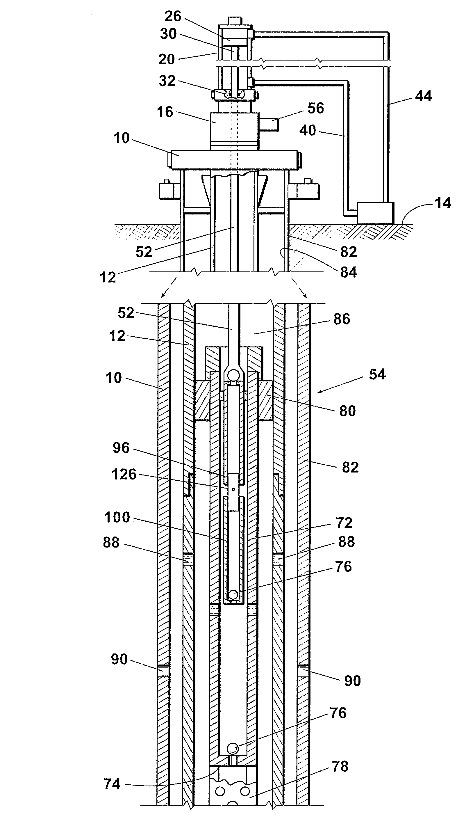
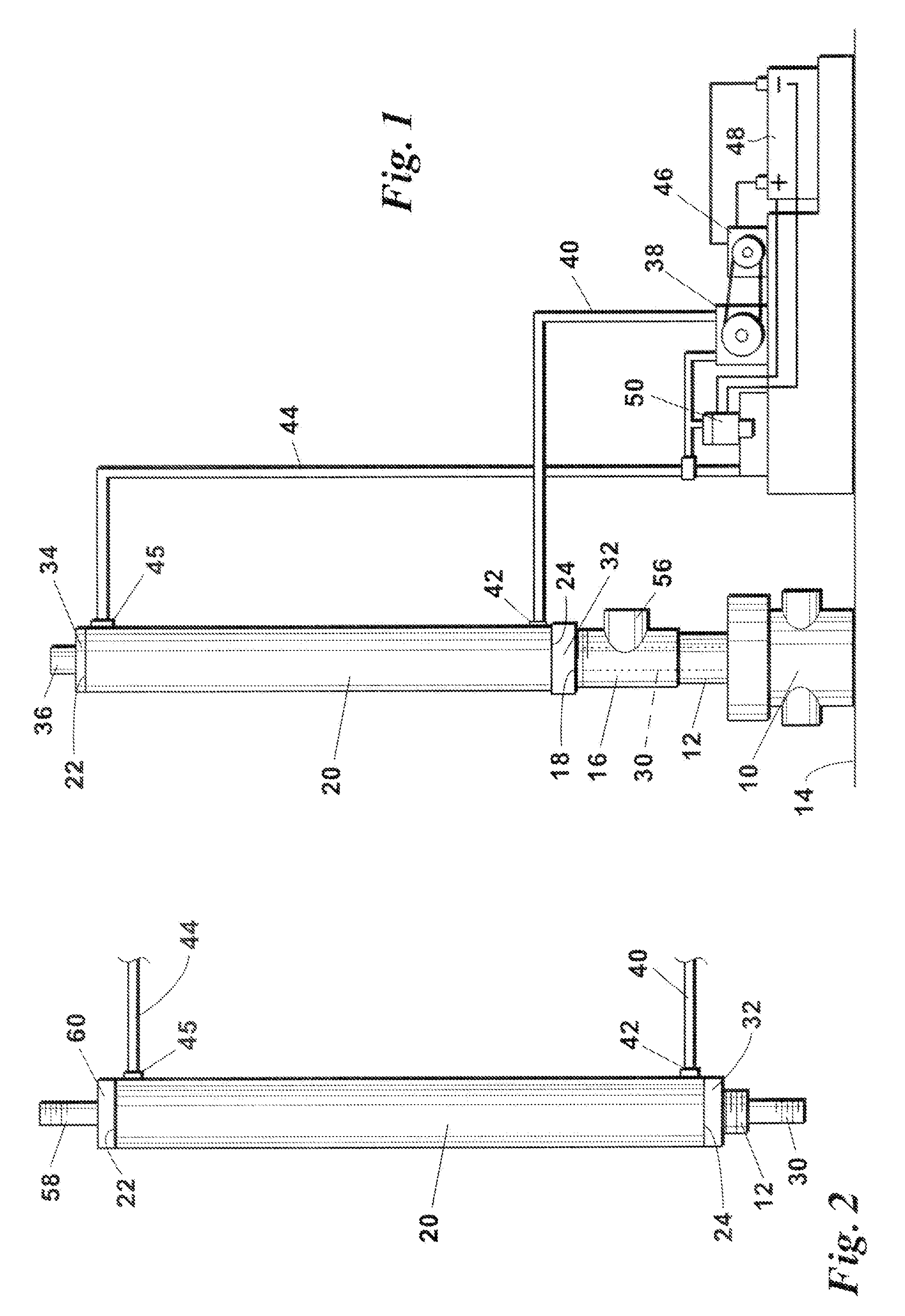
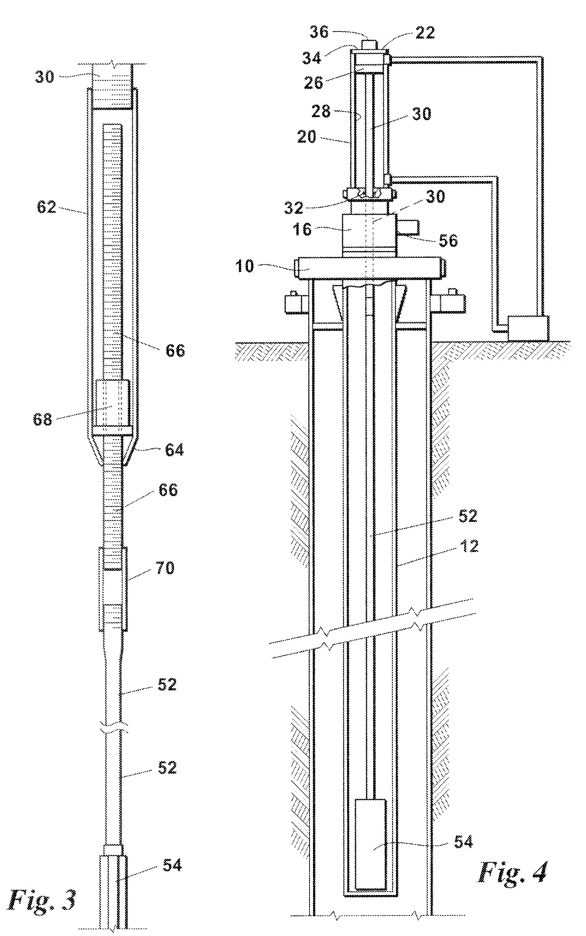
[0034]

10wellhead12tubing14earth's surface16Tee fitting18top of 1620hydraulic cylinder22top end24bottom end26piston28internal cylinder wall30downward extending piston rod32seal member34closure member36air vent38hydraulic fluid pump40pipe42inlet opening44return pipe46prime mover47battery50hydraulic controls52string of sucker rods54bottom hole pump56side opening58upwardly extending piston rod60upper seal member62tubular adjustment member64reduced diameter lower end66adjustment rod68adjustment nut7...


PUM


Abstract

A reciprocated pump positioned at the lower end of a string of tubing in a bore hole that provides a passageway for moving formation fluid to the earth's surface, including a pump barrel supported in communication with the tubing and a standing valve at the lower end thereof providing a first passageway through which formation fluid flows into the pump barrel, the pump barrel having an intermediate vent port providing a second entry passageway, and a tubular plunger reciprocated within the barrel and having an upper and a lower portion with a plurality of non-metallic seal rings separated by metallic spacers received on the plunger upper portion and configured to support a column of formation fluid within the tubing to substantially isolate the portion of the barrel below the non-metallic seal rings from the tubing pressure to thereby allow formation fluid to move into the pump barrel.

Description

REFERENCE TO PENDING APPLICATIONS[0001]This application is a continuation-in-part application which claims priority to U.S. patent application Ser. No. 11 / 103,067, filed on Apr. 11, 2005, and entitled “Improved Hydraulic Pump Jack System For Reciprocating Oil Well Sucker Rods”.REFERENCE TO MICROFICHE APPENDIX[0002]This application is not referenced in any microfiche appendix.FIELD OF THE INVENTION[0003]This invention relates to a system for reciprocating an oil well pump located in the bottom portion of a string of tubing in which the pump is reciprocated by sucker rods extending from the pump to the earth's surface, and an improved reciprocated pump for use in oil wells.BACKGROUND OF THE INVENTION[0004]Oil wells typically vary in depth from a few hundred, feet to several thousand feet. In many wells there is insufficient subterranean pressure to force the oil to the earth's surface. For this reason some system must be devised for pumping the crude oil from the producing formation t...

Claims


Application Information

Patent Timeline
Patent Type & Authority Patents(United States)
IPC IPC(8): F04B43/00E21B43/00
CPCE21B43/127F04B47/08F04B47/04F04B47/02E21B43/126
Inventor BROWN, T. LEON
Owner HENRY RES & DEV
Why Eureka
Try Eureka