Method and apparatus for manufacturing a composite material

a composite material and manufacturing method technology, applied in the field of composite material manufacturing methods and equipment, can solve the problems of inability to provide a continuous link from one side of the composite to the other, and the technique does not address the fundamental challenges of producing nano-only composite structures

Active Publication Date: 2011-11-29
AIRBUS OPERATIONS LTD
View PDF23 Cites 36 Cited by
  • Summary
  • Abstract
  • Description
  • Claims
  • Application Information

AI Technical Summary

Benefits of technology

[0010]Also, the invention enables the second layer of reinforcement elements (and optionally also the first layer) to be manufactured ex-situ, that is remotely from the liquid matrix material. This allows the reinforcement elements to be manufactured at high temperatures, up to ˜1400° C., which is significantly higher than the temperatures required to cure certain types of liquid matrix material such as liquid epoxy resin.
[0013]As well as varying the shape, size, or pattern of individual matrix layers, at least two of the layers of reinforcement elements may be different (for instance with a different shape, size, density or pattern, or a different alignment direction for the reinforcement elements). This enables the reinforcement layers to be built up as a “net shape”, as well as enabling the reinforcement properties of the material to be varied between layers.

Problems solved by technology

Although such techniques connect consecutive layers of the composite, they fail to provide a continuous link from one side of the composite to the other because the layers of CNTs do not overlap with each other.
Also, such techniques do not address the fundamental challenges of producing nano-only composite structures; namely full dispersion with alignment and optimised bonding.

Method used


Image

  • Method and apparatus for manufacturing a composite material
  • Method and apparatus for manufacturing a composite material
  • Method and apparatus for manufacturing a composite material

Examples


Embodiment Construction

)

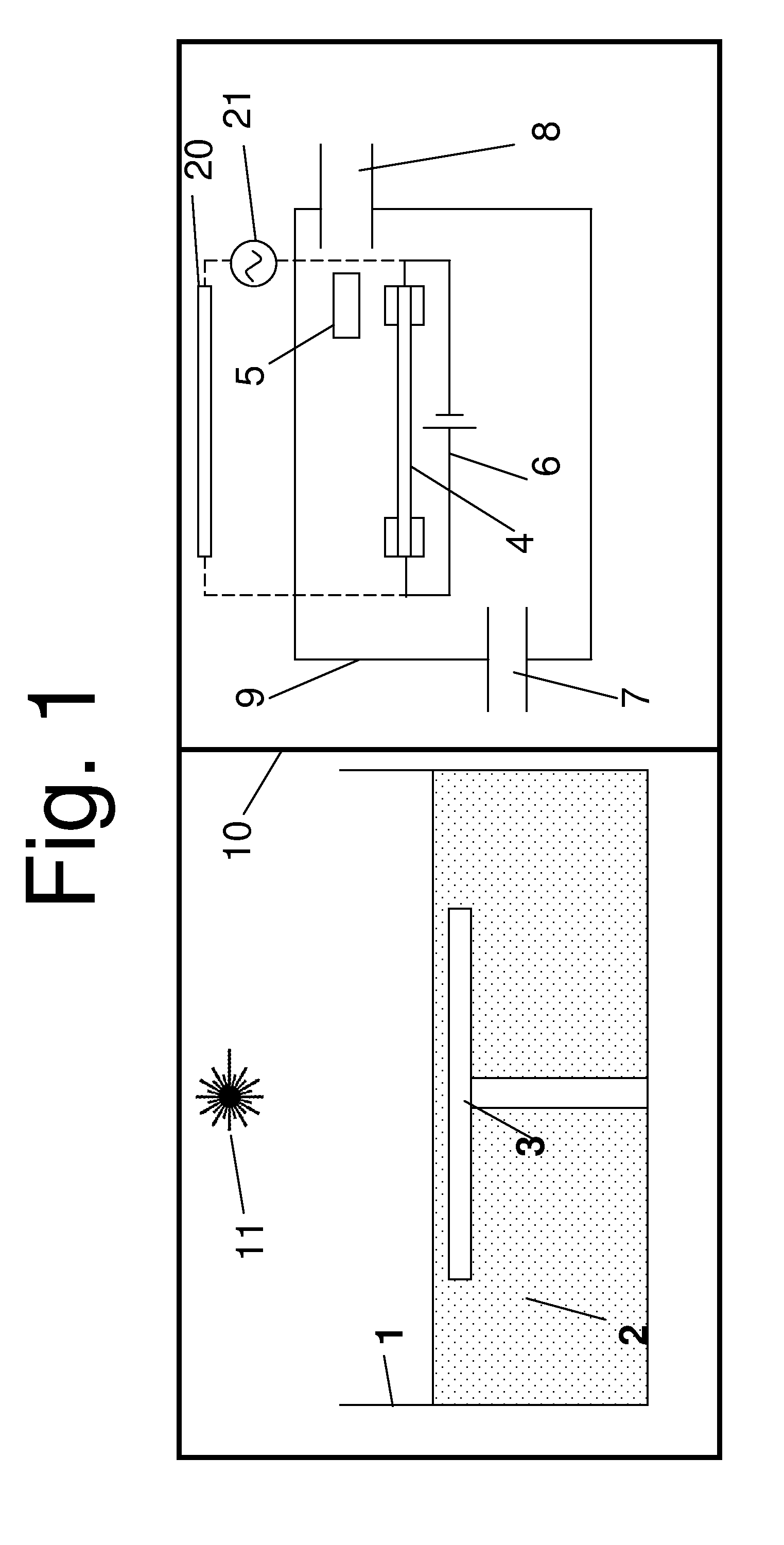
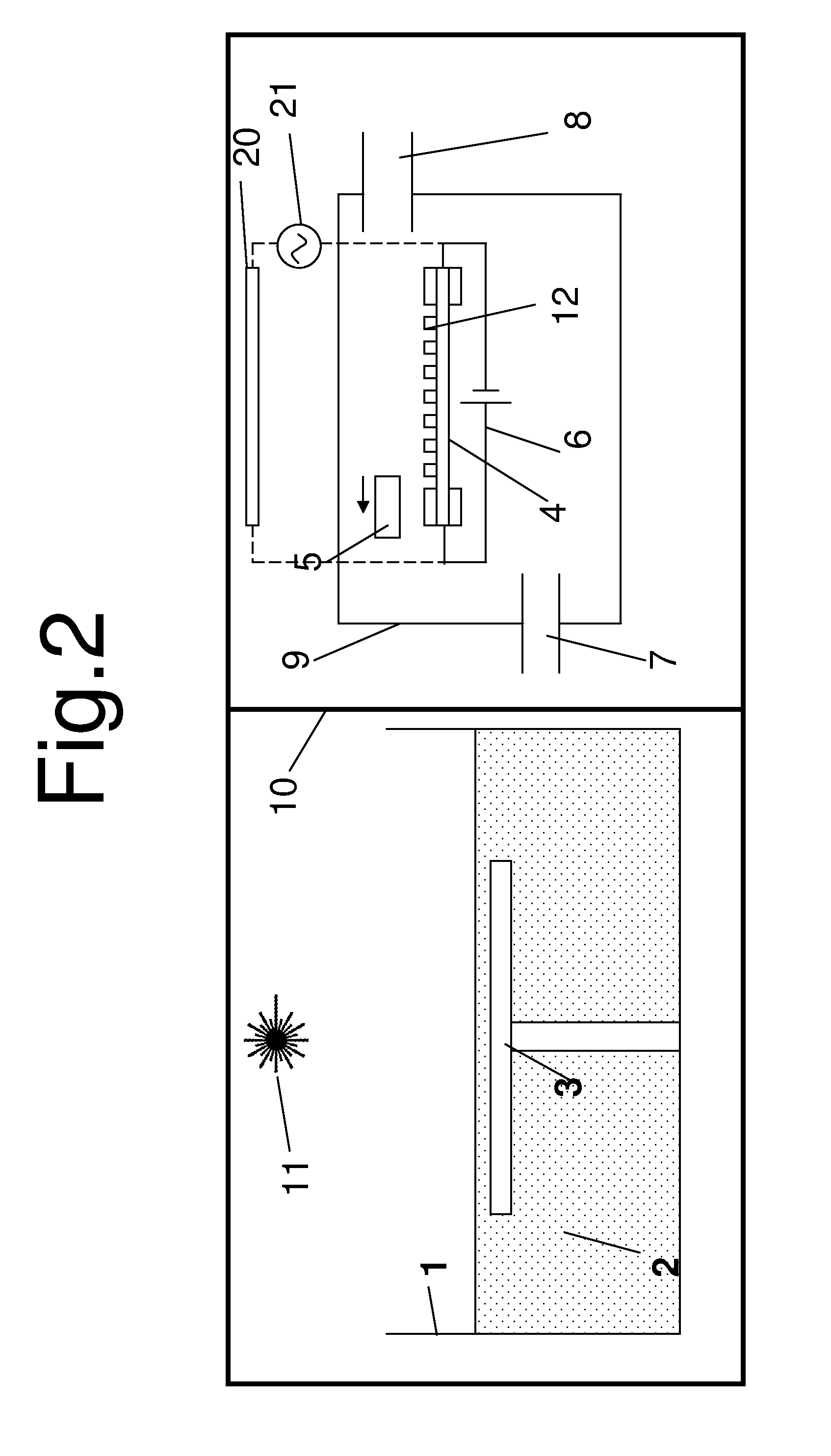
[0057]FIG. 1 is a schematic diagram showing an additive layer manufacturing (ALM) chamber on the left hand side of the figure, and a chemical vapour deposition-carbon nanotube (CVD-CNT) growth chamber on the right hand side. These two chambers are separated by a door 10.

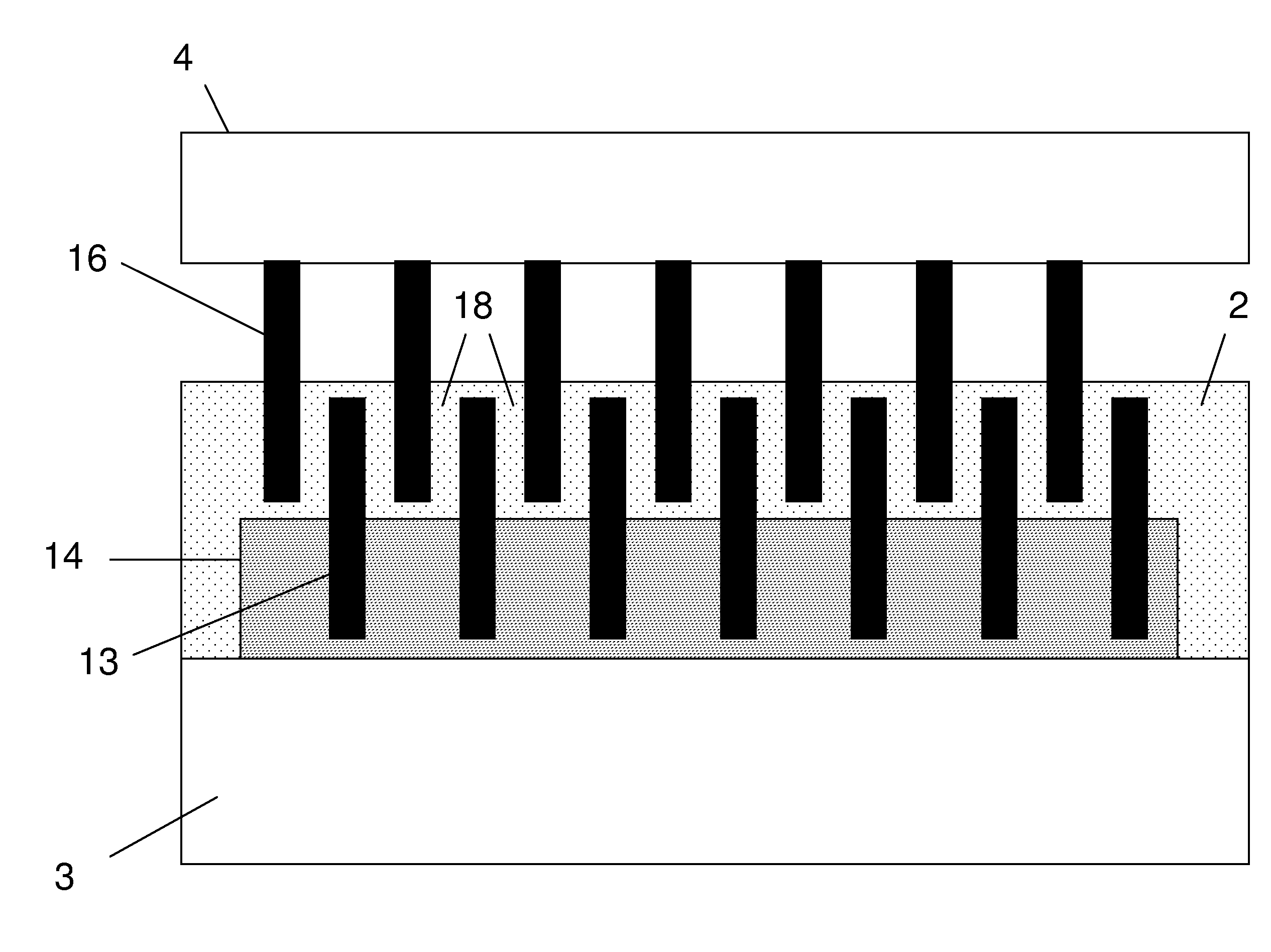
[0058]The ALM chamber comprises a vat 1 containing an un-cured liquid photo curing resin 2. A build platform 3 is mounted in the vat 1 and can be moved up and down as required.

[0059]The CVD-CNT chamber contains a silicon transfer body 4 which is connected to an electrical heating circuit 6. The chamber has a gas input 7, a gas output 8 and a door 9.

[0060]Referring to FIG. 2, a catalyst deposition system 5 deposits catalyst material 12 onto the silicon transfer body 4 in a predefined shape, pattern and density. The system 5 may comprise a printing head which sprays an array of colloid drops onto the transfer body 4, and as the colloid evaporates, metal catalyst particles suspended in the colloid drops are deposited. ...


PUM

PropertyMeasurementUnit
angleaaaaaaaaaa
temperaturesaaaaaaaaaa
aspect ratioaaaaaaaaaa

Abstract

A method of manufacturing a composite material, the method comprising: providing a first layer (14) of CNTs reinforcement elements (13) with liquid matrix material in interstitial gaps between the reinforcement elements; dipping a second layer of reinforcement elements into the liquid matrix material in the interstitial gaps such that the reinforcement elements in the second layer become partially embedded in the first layer of reinforcement elements and partially protrude from the first layer of reinforcement elements, impregnating the protruding parts of the reinforcement elements in the second layer with liquid matrix material; and curing the liquid matrix material.

Description

[0001]This application is the U.S. national phase of International Application No. PCT / GB2008 / 050655 filed 4 Aug. 2008, which designated the U.S. and claims priority to GB Application No. 0715164.0 filed 6 Aug. 2007, the entire contents of each of which are hereby incorporated by reference.FIELD OF THE INVENTION[0002]The present invention relates to a method and apparatus for manufacturing a composite material.BACKGROUND OF THE INVENTION[0003]“Nanostitching” of fibre composites using aligned carbon nanotubes (CNTs) is described in Chemical, Mechanical, and Thermal Control of Substrate-Bound Carbon Nanotube Growth, Extended Abstract of Doctoral Thesis, Anastasios John Hart, December 2006. This document is available online at:[0004]pergatory.mitedu / ajhart / research / documents / ajhart_phdthesisextendedabstract_jan07.pdf[0005]Consecutive layers in fibre composites are connected by aligned CNTs which are primarily perpendicular to the fibre surface.[0006]Although such techniques connect con...

Claims


Application Information

Patent Timeline
Patent Type & Authority Patents(United States)
IPC IPC(8): B05D1/18C08F2/46
CPCB29C70/12B29C70/28B82Y30/00B29K2707/00Y10T428/292Y10S977/89Y10S977/786B29K2707/04
Inventor FARMER, BENJAMIN LIONELJOHNS, DANIEL MARK
Owner AIRBUS OPERATIONS LTD
Why Eureka
Try Eureka