
Optical recording medium

a recording medium and optical technology, applied in the field of recording optical recording media, can solve the problems of deterioration of wobble signal quality, high jitter, etc., and achieve the effect of reducing cross talk, optimum optical absorption/thermal decomposition properties, and sufficient reflectance and modulation degrees

Inactive Publication Date: 2011-11-29
RICOH KK
View PDF12 Cites 1 Cited by
  • Summary
  • Abstract
  • Description
  • Claims
  • Application Information

AI Technical Summary

Benefits of technology

The solution provides optical recording media with superior recording signal properties, reduced cross-talk between tracks, and enhanced durability, suitable for high-speed recording by optimizing the film thickness and thermal decomposition properties of the dye layers.

Problems solved by technology

In addition, the film thickness of dye-recording layers formed at convex portions is similar to or somewhat thinner than the film thickness of dye-recording layers formed at concave portions between the tracks, therefore, heat due to laser irradiation and / or dye decomposition transfers to adjacent tracks, resulting in higher jitter and / or deterioration of wobble signal quality.

Method used


Image

  • Optical recording medium
  • Optical recording medium
  • Optical recording medium

Examples


example 1

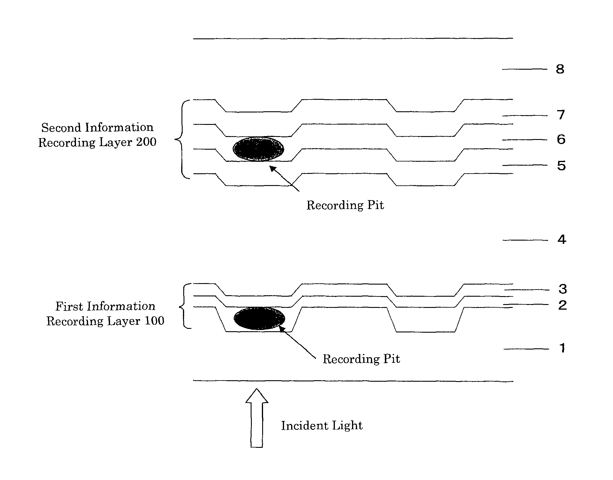
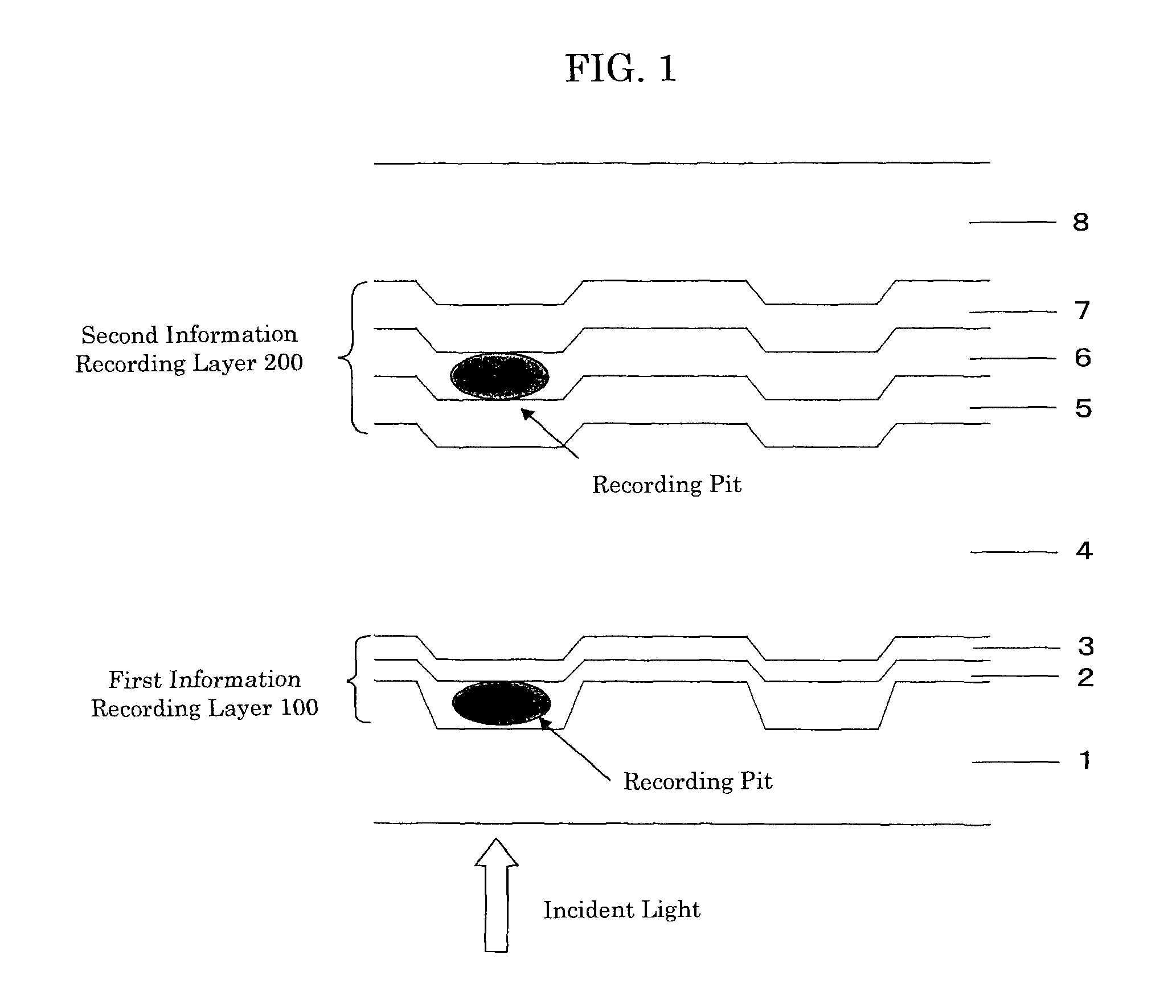
[0115]A coating liquid containing a squarylium compound of Compound (1) shown below dissolved in 2,2,3,3-tetrafluoropropanol was spin-coated on a polycarbonate substrate of 0.57 mm thick having concave grooves of 160 nm deep, 0.25 μm wide at bottom and 0.74 μm track-pitch to thereby form a first dye recording layer of about 40 nm thick.

[0116]Then an Ag alloy with 0.5 atom % of In was sputtered on the first dye recording layer to form a translucent reflective layer of 9 nm thick, thereby to form a first information substrate having a first information recording layer.

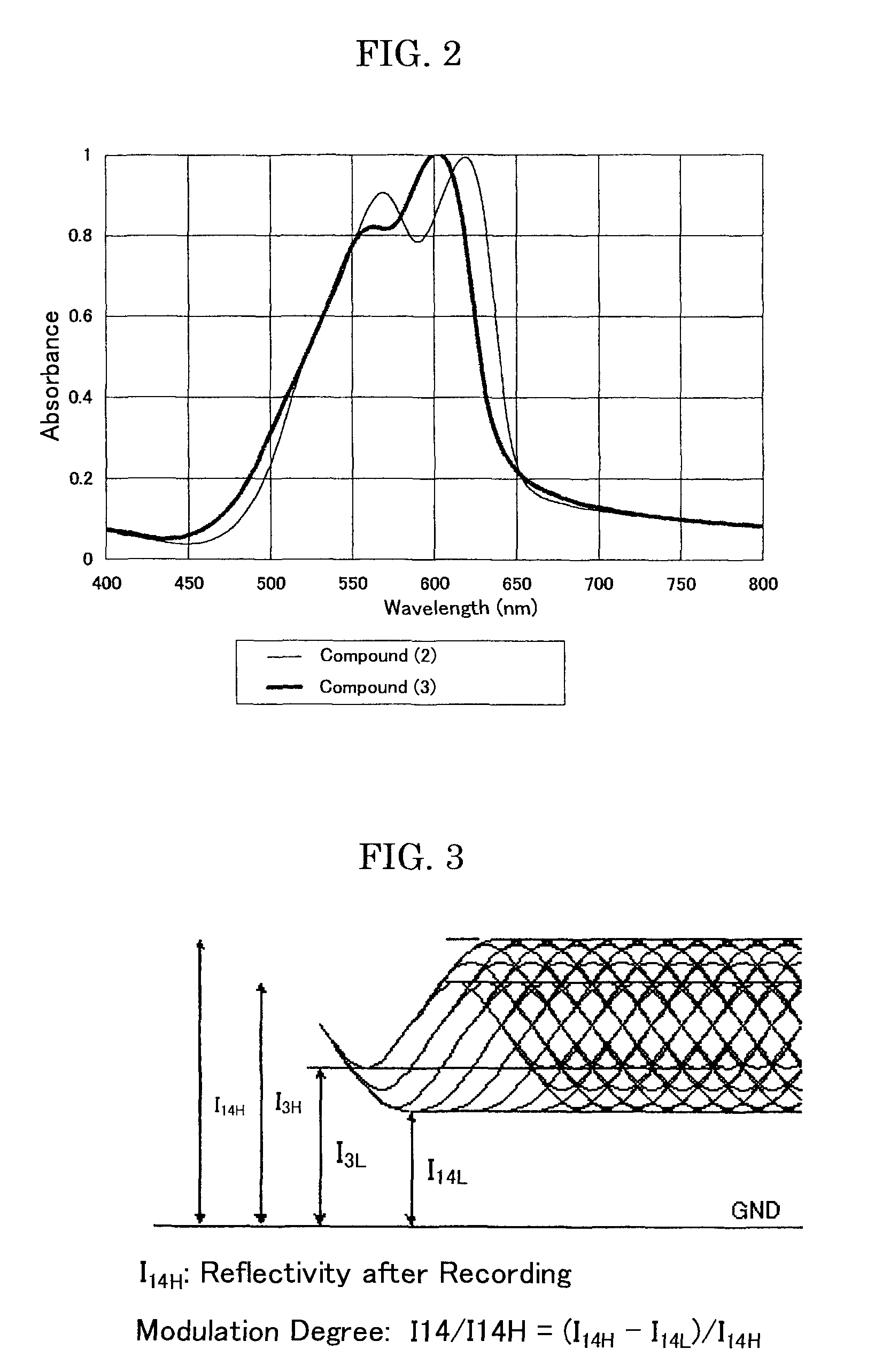
[0117]Thereafter, an Ag light reflective layer of 120 nm thick was formed by sputtering on a polycarbonate substrate of 0.60 mm thick having convex grooves of 34 nm deep, 0.25 μm wide at bottom and 0.74 μm track-pitch, then onto which a coating liquid, containing a cyanine dye of Compound (2) shown below and a squarylium compound of Compound (3) shown below dissolved in 2,2,3,3-tetrafluoropropanol in an weight ratio of 6...

example 2

[0122]In a similar manner as Example 1, a coating liquid of a squarylium compound of Compound (1) dissolved in 2,2,3,3-tetrafluoropropanol was spin-coated on a polycarbonate substrate of 0.57 mm thick having concave grooves of 160 nm deep, 0.25 μm wide at bottom and 0.74 μm track-pitch to thereby form a first dye recording layer of about 40 nm thick. Then an Ag alloy with 0.5 atom % of In was sputtered on the first dye recording layer to form a translucent reflective layer of 9 nm thick, thereby to form a first information substrate having a first information recording layer.

[0123]Thereafter, an Ag light reflective layer of 120 nm thick was formed by sputtering on a polycarbonate substrate of 0.60 mm thick having convex grooves of 34 nm deep, 0.25 μm wide at bottom and 0.74 μm track-pitch, then onto which a coating liquid, containing a cyanine dye of Compound (2) and a squarylium compound of Compound (4) shown below dissolved in 2,2,3,3-tetrafluoropropanol in an weight ratio of 6 / 4 ...


PUM

PropertyMeasurementUnit
thicknessaaaaaaaaaa
temperatureaaaaaaaaaa
decomposition temperatureaaaaaaaaaa

Abstract

Provided is an optical recording medium including, in sequence:a first substrate; a first information recording layer; an intermediate layer; a second information recording layer; and a second substrate having wobble convex portions on its surface,wherein information is recorded on or reproduced from the first information recording layer and second information recording layer by irradiation with a laser beam from a first information recording layer side,wherein the second information recording layer includes, over the second substrate, a light reflective layer, a dye recording layer, and an inorganic protective layer,wherein the inorganic protective layer has a thickness of 3 nm to 40 nm, and wherein the dye recording layer includes a cyanine compound expressed by General Formula (I) and a squarylium compound expressed by General Formula (II):

Description

TECHNICAL FIELD[0001]The present invention relates to recordable optical recording media capable of recording and regenerating information, in which light beam is irradiated onto dye-recording layers to cause optical change such as of transmittance and reflectance, in particular to two-layer DVDs (Digital Video Disc or Digital Versatile Disc) with two recordable information recording layers.BACKGROUND ART[0002]Recordable DVDs such as DVD+RW, DVD+R, DVD-R, DVD-RW and DVD-RAM are commercially available in addition to playback-only optical recording media such as DVD-ROM. The DVR+R and DVD+RW are developed on the basis of conventional CD-R and CD-RW (recording compact disc) such that the recording density (track pitch, signal mark length) and substrate thickness are compatible between CD and DVD conditions in order to assure the reproduction compatibility with playback-only DVD.[0003]For example, DVD+Rs have a construction, similarly with CD-Rs, that an optical recording layer is provi...

Claims


Application Information

Patent Timeline
Patent Type & Authority Patents(United States)
IPC IPC(8): G11B7/24G11B7/24024G11B7/24041G11B7/2472G11B7/254G11B7/257G11B7/2578G11B7/258G11B7/259
CPCG11B7/246G11B7/2472G11B7/2492G11B7/2533G11B7/2534G11B7/2536G11B7/2578G11B7/259G11B2007/24612G11B2007/25706G11B2007/25708G11B2007/2571G11B2007/25715G11B2007/25716G11B7/24038G11B7/245G11B7/2467G11B7/248G11B7/2531
Inventor NAKAMURA, YUKIHAYASHI, MASAHIROMIZUKAMI, SATOSHIYASHIRO, TOHRU
Owner RICOH KK
Learn More