Scaling in a receiver for coded digital data symbols

a digital data and receiver technology, applied in the field of receiving coded digital data symbols, can solve the problems of limited bit width to represent data values in the terminal, limited bit width available for the processing of this estimate, and limited computational resources of terminals for use with such communications networks

Active Publication Date: 2011-11-29
TELEFON AB LM ERICSSON (PUBL)
View PDF10 Cites 0 Cited by
  • Summary
  • Abstract
  • Description
  • Claims
  • Application Information

AI Technical Summary

Benefits of technology

[0015]Alternatively, when the step of calculating estimates comprises the step of multiplying for a number of channels despread data symbols by the conjugate value of a channel estimate and summing multiplying results for said number of channels, the step of generating scaled estimates may comprise the step of multiplying each channel estimate or its conjugate value by said scaling factor. In this way the number of scaling multiplications is reduced considerably, because the channel estimate is typically changed at a lower rate than the data rate.
[0018]In a further embodiment, the method further comprises the step of filtering said averaged amplitude values. In this way it is ensured that the scaling factor fluctuates more slowly, so that the soft information over a longer time interval is not destroyed.
[0020]As mentioned, the invention also relates to a receiver for receiving coded digital data symbols sent from a transmitter through a transmission channel of a communications network, the receiver being arranged to calculate estimates of sent data symbols, each of said estimates being represented by a first number of bits, and provide from said calculated estimates modified estimates represented by a second number of bits, said second number being lower than said first number. When the receiver is further arranged to calculate an amplitude value for each of said calculated estimates; calculate an averaged amplitude value for a number of said amplitude values; calculate a scaling factor from said averaged amplitude value; and generate scaled estimates of sent data symbols in dependence of said scaling factor, said scaling factor being used for a number of scaled estimates corresponding to the number of amplitude values for which the averaged amplitude value was calculated, a receiver, which provides a better scaling factor for most channel cases, and which can still be used with the limited computational resources of a terminal of the type described above, is achieved.
[0023]Alternatively, when the receiver is arranged to calculate estimates by multiplying for a number of channels despread data symbols by the conjugate value of a channel estimate and summing multiplying results for said number of channels, the receiver may further be arranged to generate scaled estimates by multiplying each channel estimate or its conjugate value by said scaling factor. In this way the number of scaling multiplications can be reduced considerably, because the channel estimate is typically changed at a lower rate than the data rate.
[0026]In a further embodiment, the receiver is further arranged to filter said averaged amplitude values. In this way it is ensured that the scaling factor fluctuates more slowly, so that the soft information over a longer time interval is not destroyed.

Problems solved by technology

Furthermore, the timing of the demodulation must be synchronized, i.e. the despreading code must be applied to the received signal at the correct instant in time, which can be difficult due to the multipath effects mentioned above.
Terminals for use with such communications networks are normally limited in size and computational resources.
One result of this limitation is that there is only a limited bit width to represent data values in a terminal.
However, the bit width available for the processing of this estimate will also be limited and probably smaller than the sum of the two other bit widths.
However, since the signal level in the receiver typically changes very rapidly, a fixed factor will not be optimal, and it is generally not possible to find a scaling factor that is suitable in all situations.
Although these adaptive algorithms may be able to provide optimal scaling factors in most situations, they are quite complex and require considerable computational resources, and as mentioned before such resources are rarely available in the terminals concerned here.
However, with the histogram it is necessary to average over a long time, which is not expedient because the channel can change very fast.
Although reference is here made to a scaling factor and truncation, the same problem exists for other rounding methods as well.

Method used


Image

  • Scaling in a receiver for coded digital data symbols
  • Scaling in a receiver for coded digital data symbols
  • Scaling in a receiver for coded digital data symbols

Examples


Embodiment Construction

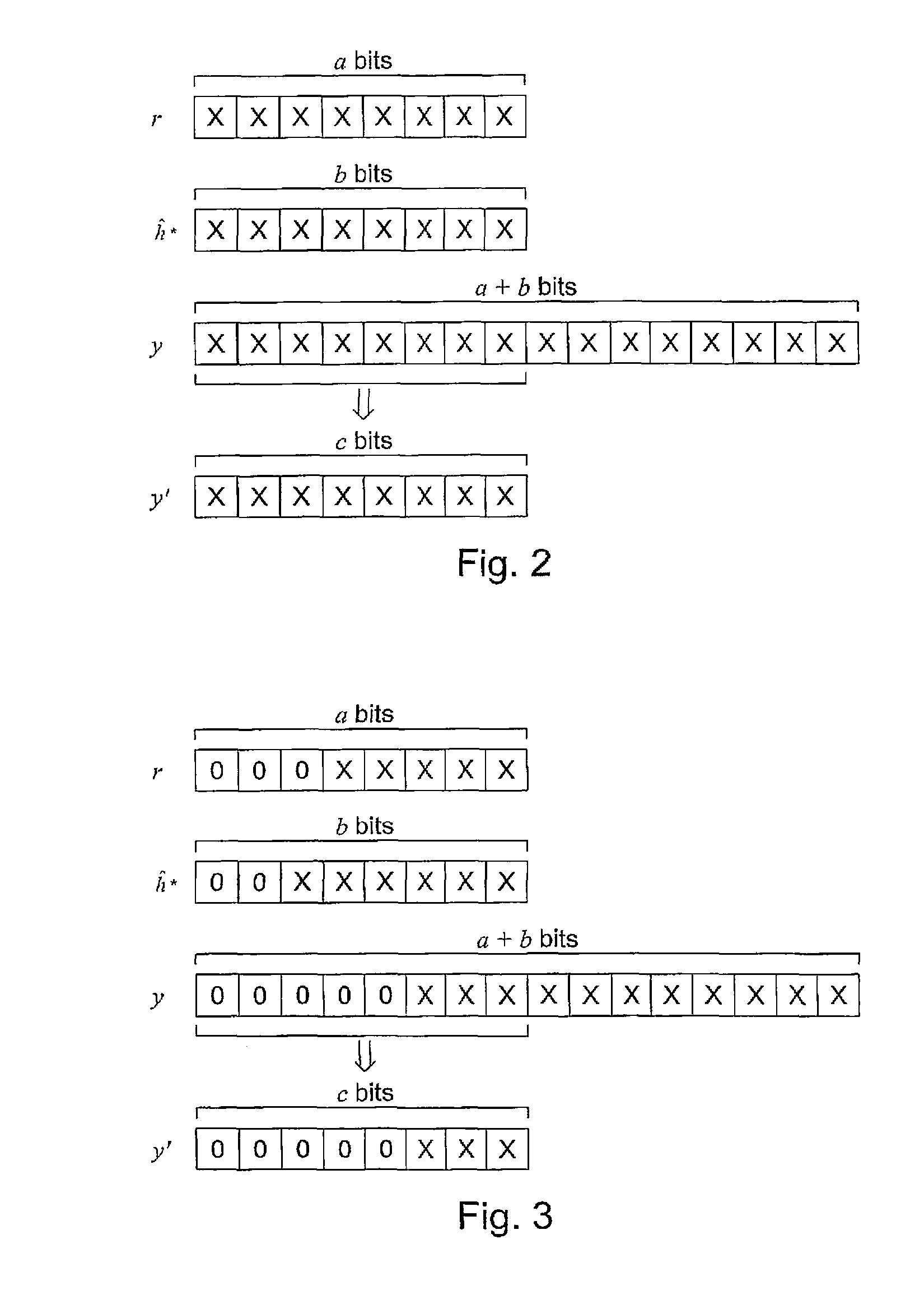
s="d_n">[0032]FIG. 2 shows how an estimate having 16 bits may be truncated so that the eight most significant bits remain,

[0033]FIG. 3 shows the situation of FIG. 2, when the estimate has a number of leading zeros,

[0034]FIG. 4 shows a situation in which the leading zeros are not included in the selected bits,

[0035]FIG. 5 shows how the estimate may be multiplied by a scaling factor before truncation,

[0036]FIG. 6 shows a different way in which the estimate may be multiplied by a scaling factor before truncation,

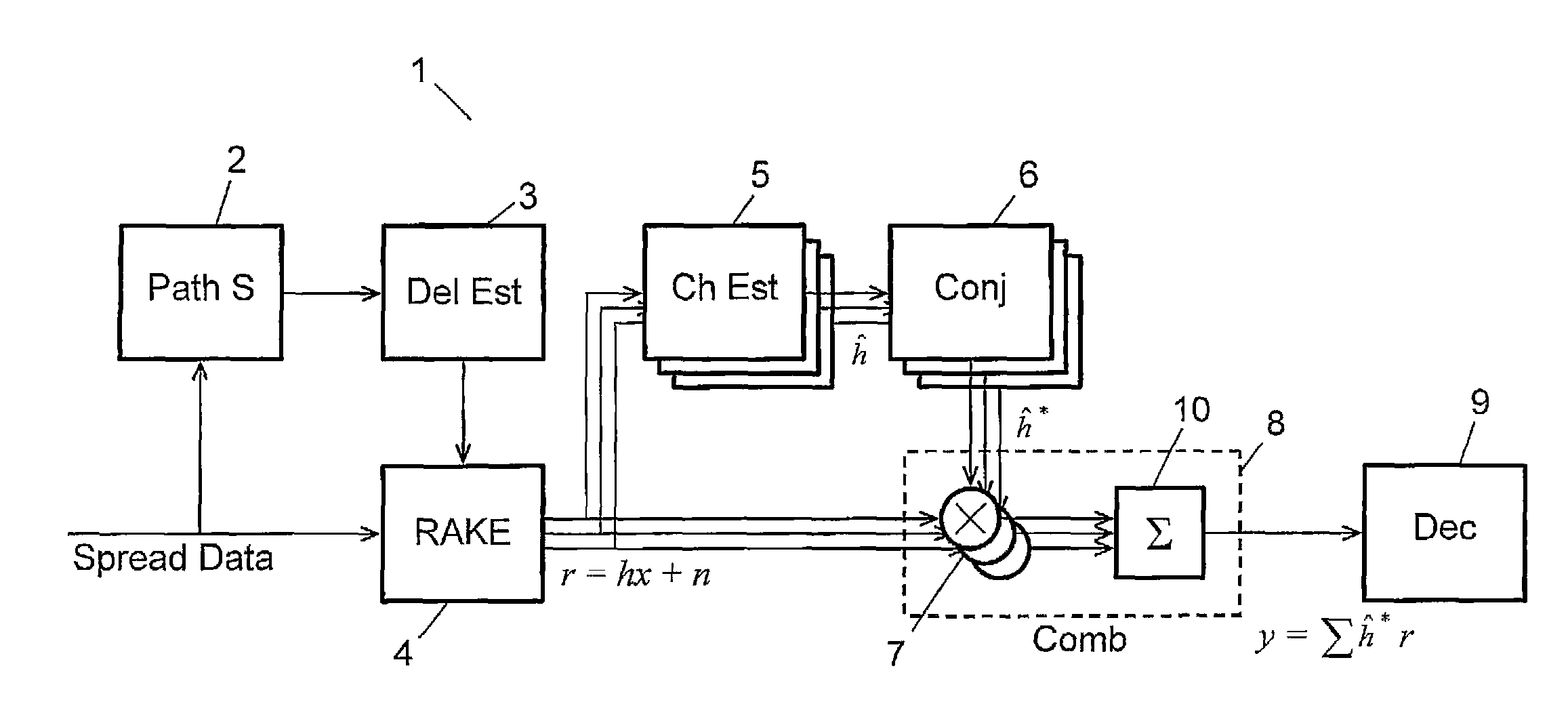
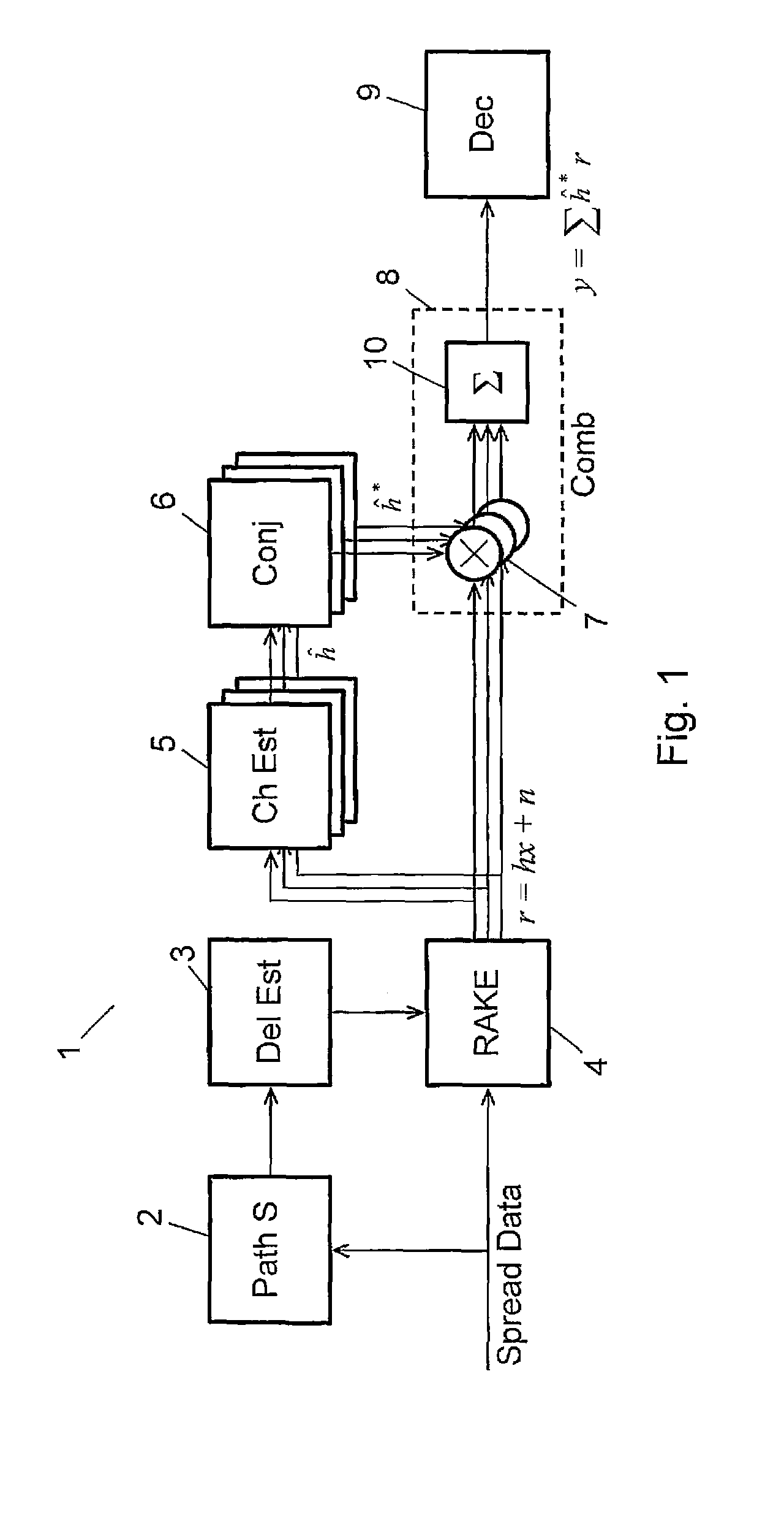
[0037]FIG. 7 shows a part of the circuit of FIG. 1 with a scaling unit and a truncation unit added,

[0038]FIG. 8 shows an embodiment of the invention in which the symbol estimates are scaled,

[0039]FIG. 9 shows an embodiment of the invention in which multiplication results are scaled,

[0040]FIG. 10 shows an embodiment of the invention in which the channel estimate is scaled, and

[0041]FIG. 11 shows a different embodiment in which the channel estimate is scaled.

DETAILED DESCRIPTION ...


PUM


Abstract

Coded digital data symbols sent through a transmission channel of a communications network are received in a receiver. Estimates (y) represented by a first number (a+b) of bits are calculated, and modified estimates (y′) represented by a second number (c) of bits provided therefrom, the second number being lower than the first number. An amplitude value is calculated for each estimate (y), and an averaged amplitude value calculated for a number of amplitude values. A scaling factor (s) is calculated form the averaged amplitude value, and scaled estimates generated in dependence of die scaling factor. The scaling factor is used for a number of scaled estimates corresponding to the number of amplitude values for which the averaged amplitude value was calculated. Thus a better scaling factor is provided for most channel cases, which can still be calculated with the limited computational resources of a terminal for such networks.

Description

[0001]This application claims the benefit of U.S. Provisional Application No. 60 / 638,438, filed 22 Dec. 2004, the disclosure of which is fully incorporated herein by reference.TECHNICAL FIELD OF THE INVENTION[0002]The invention relates to a method of receiving coded digital data symbols sent from a transmitter through a transmission channel of a communications network, the method comprising the steps of calculating estimates of sent data symbols, each of said estimates being represented by a first number of bits; and providing from said calculated estimates modified estimates represented by a second number of bits, said second number being lower than said first number. The invention further relates to a receiver for receiving coded digital data symbols sent from a transmitter through a transmission channel of a communications network.DESCRIPTION OF RELATED ART[0003]When coded digital data symbols are transmitted via a radio link the transmitted signals typically propagate over multi...

Claims


Application Information

Patent Timeline
Patent Type & Authority Patents(United States)
IPC IPC(8): H04B1/00H04L7/00H04N7/173H04B1/707
CPCG06F7/49936H04B1/712H04B7/0842G06F7/523H04B2201/70707H04B2201/709727
Inventor CEDERGREN, ANDREASJONSSON, ELIAS
Owner TELEFON AB LM ERICSSON (PUBL)
Why Eureka
Try Eureka