
Vehicle diagnostic system

a diagnostic system and vehicle technology, applied in the direction of vehicle position/course/altitude control, process and machine control, instruments, etc., can solve the problems of multiple failure codes, failure of individual systems or components, and diagnostic computers that are not able to analyze data to identify the ultimate failure source plaguing the particular vehicle, etc., to achieve the effect of easy dissemination of diagnostic data

Active Publication Date: 2011-11-29
INNOVA ELECTRONICS
View PDF66 Cites 72 Cited by
  • Summary
  • Abstract
  • Description
  • Claims
  • Application Information

AI Technical Summary

Benefits of technology

[0013]It is contemplated that the present invention may provide more accurate and reliable diagnostic information than is available by known systems and methods. The logged diagnostic data related to the vehicle components associated with the most likely solution may be compared with the prioritized result obtained from the prior experience database to confirm that the most likely failure source is the actual failure source. Furthermore, it is also understood that data that is obtained during the above-described method may be communicated to several remote locations in order to provide the operator of the vehicle with a diagnostic support network. For instance, the most likely failure source may be communicated to the driver's cell phone to alert the driver of the problem with the vehicle. In addition, the most likely failure source may be communicated to a customer support center. In this manner, the customer support center may begin diagnostic support tailored to the specific needs of that vehicle without requiring the operator to call into the customer support center in order to receive diagnostic assistance. It may be desirable to wirelessly communicate data from the automotive diagnostic tool in order to more easily disseminate the diagnostic data.

Problems solved by technology

Over time, repeated use of the vehicle may cause failure of individual systems or components.
Although the onboard diagnostic computers may log data generated in response to operation of the vehicle, the diagnostic computer may not be capable of analyzing the data to identify the ultimate failure source plaguing the particular vehicle.
However, given the complex nature of today's vehicles, several failure codes may be generated at any given time.
In other words, the failure of one particular system or component may cause other systems or components to operate incorrectly.
However, additional information may be required before the vehicle can be completely repaired.

Method used


Image

  • Vehicle diagnostic system
  • Vehicle diagnostic system
  • Vehicle diagnostic system

Examples


Embodiment Construction

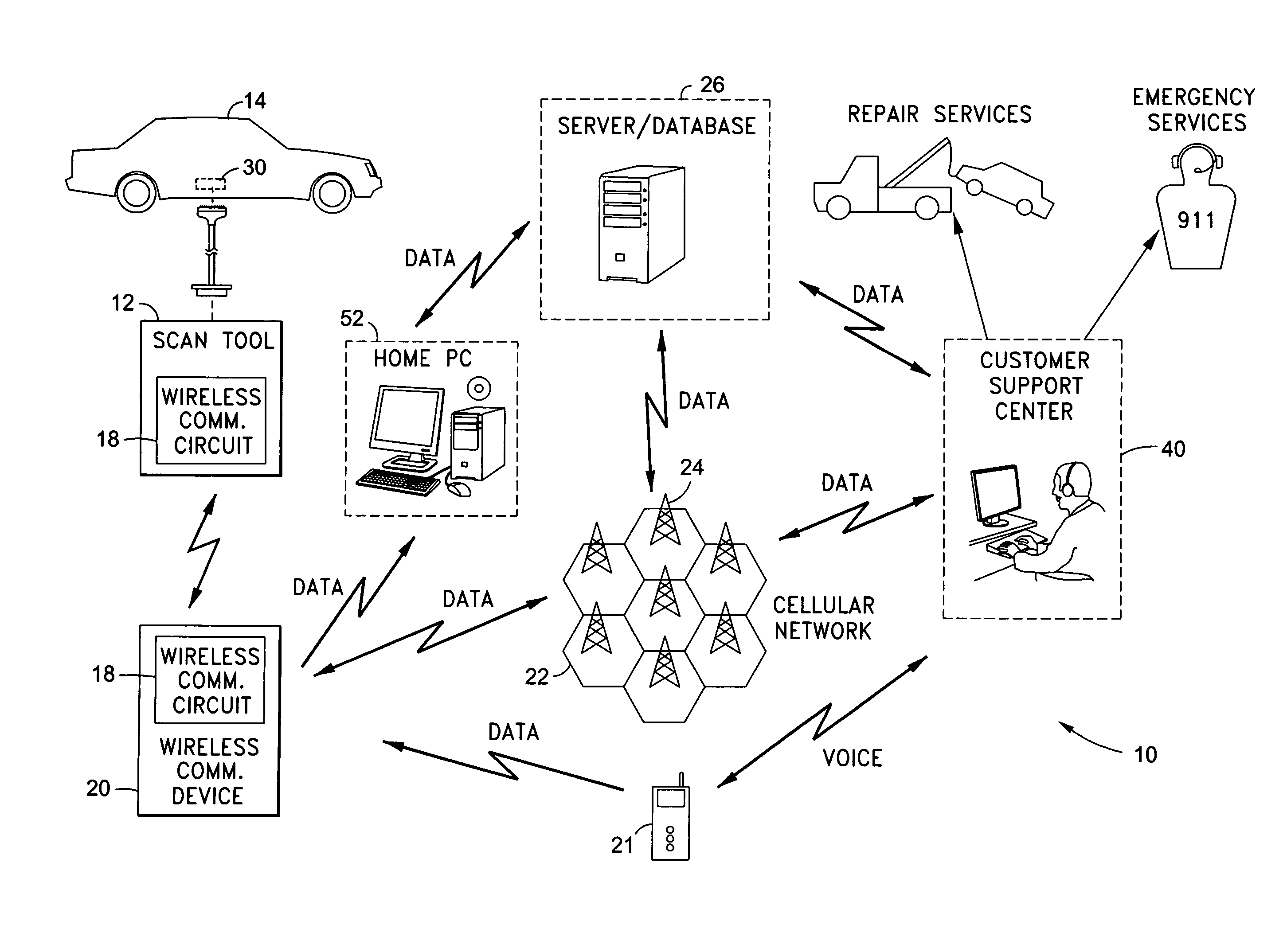
[0022]Referring now to the drawings wherein the showings are for purposes of illustrating a preferred embodiment of the present invention only, and not for purposes of limiting the same. FIG. 1 shows a vehicle support network 10 constructed in accordance with an aspect of the present invention. The vehicle support network 10 includes a variety of components which collectively provide diagnostic and operational support for a vehicle 14.

[0023]As depicted in FIG. 1, vehicle 14 is equipped with an onboard diagnostic computer 30. The diagnostic computer 30 is in communication with many of the systems and components included in the vehicle 14. Exemplary components and systems may include, but are not limited to components and systems related to the vehicle's braking, velocity, acceleration, exhaust, engine temperature, power steering, engine speed, etc. It is understood that other systems and components may additionally be in communication with the onboard diagnostic computer 30.

[0024]Eac...


PUM


Abstract

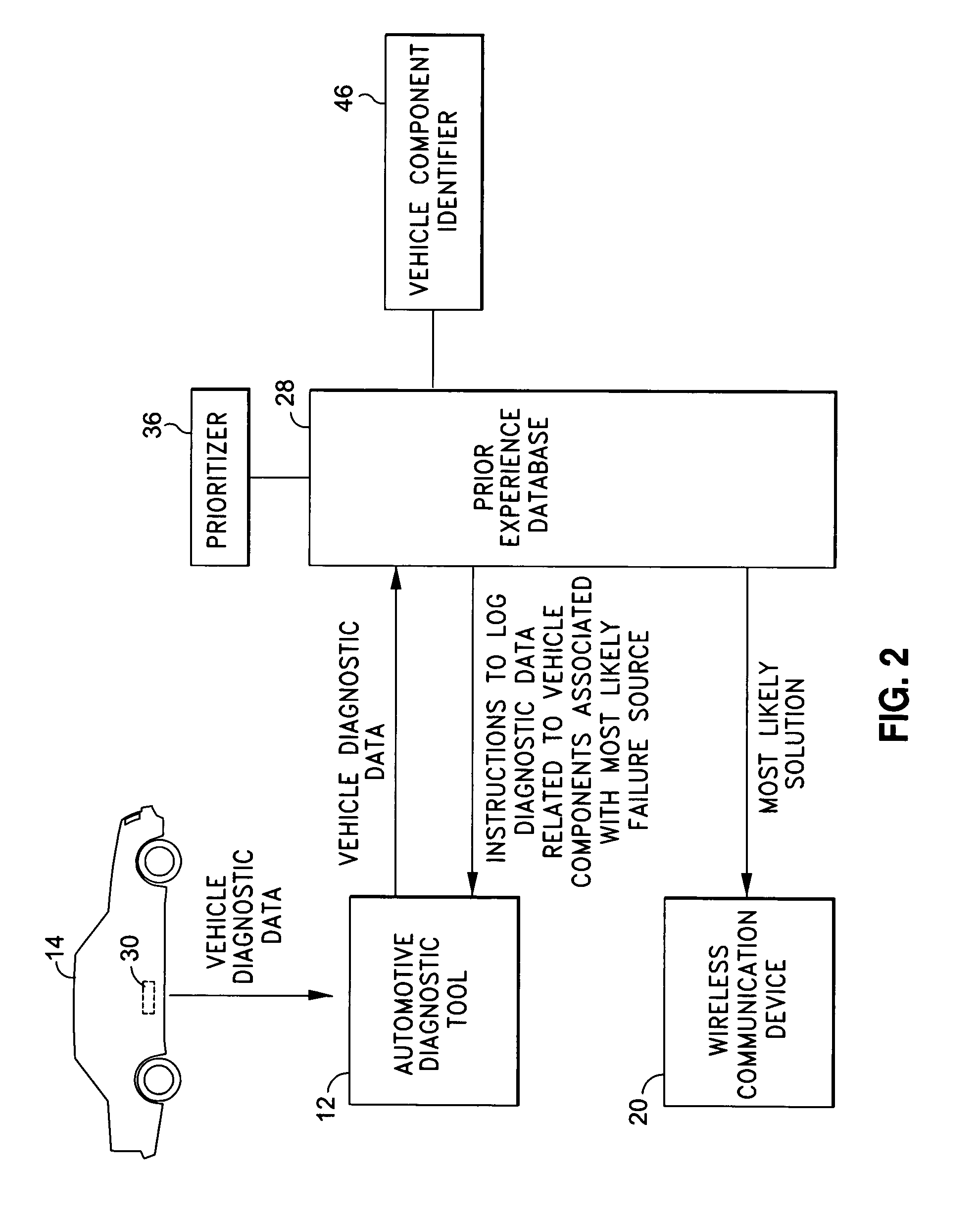
There is provided a method of providing vehicle support. The method includes receiving diagnostic data from the onboard vehicle computer. The diagnostic data is received by an automotive diagnostic tool and is then communicated to a prior experience database having information related to diagnostic solutions associated with combinations of diagnostic data. The prior experience database is arranged to match the received diagnostic data to possible diagnostic solutions. The diagnostic solutions are then prioritized in accordance with ranked matches of the received diagnostic data to the previous combinations of diagnostic data stored in the prior experience database. The possible diagnostic solution associated with the highest ranked combination of diagnostic data is identified as the most likely solution. Vehicle components associated with the most likely solution are then identified. The diagnostic tool is subsequently configured to log diagnostic data related to the vehicle components associated with the most likely solution.

Description

CROSS-REFERENCE TO RELATED APPLICATIONS[0001]The present application is a continuation-in-part of U.S. application Ser. No. 11 / 166,719 entitled AUTOMOTIVE DATA LOGGER filed Jun. 24, 2005, now abandoned U.S. application Ser. No. 11 / 172,293 entitled CELLPHONE BASED VEHICLE DIAGNOSTIC SYSTEM filed Jun. 30, 2005, and U.S. application Ser. No. 11 / 823,757 entitled AUTOMOTIVE DIAGNOSTIC AND REMEDIAL PROCESS filed Jun. 28, 2007, the disclosures of which are incorporated herein by reference.STATEMENT RE: FEDERALLY SPONSORED RESEARCH / DEVELOPMENT[0002](Not Applicable)BACKGROUND OF THE INVENTION[0003]1. Field of the Invention[0004]The present invention relates generally to vehicle support systems and more specifically to a method of providing a vehicular diagnostic evaluation based on an analysis of vehicle operation data.[0005]2. Description of the Related Art[0006]Many of today's vehicles include a wide range of systems and components that perform various operations while the vehicle is in us...

Claims


Application Information

Patent Timeline
Patent Type & Authority Patents(United States)
IPC IPC(8): G06F19/00
CPCG07C5/008G07C5/0808G07C5/085
Inventor CHEN, IEON C.ANDREASEN, KEITHPHAM, PHUONGMADISON, ROBERT
Owner INNOVA ELECTRONICS
Learn More