Waste water immersion probe

a technology of waste water and probe, which is applied in the direction of vehicle maintenance, material testing goods, applications, etc., can solve the problems of shaft sealing only having a limited sealing effect or reliably sealing, affecting the accuracy etc., to achieve low axial friction force and avoid waste water immersion. , the effect of reducing the risk of waste water immersion

Active Publication Date: 2011-12-06
HACH LANGE HACH LANGE
View PDF18 Cites 18 Cited by
  • Summary
  • Abstract
  • Description
  • Claims
  • Application Information

AI Technical Summary

Benefits of technology

[0005]In view of this, it is an object of the invention to provide a waste water immersion probe with improved sealing.
[0007]A contactless and shaft-free mechanical coupling of the drive motor with the wiper is thus realized, making a housing opening for a drive shaft dispensable. By the omission of the housing opening for the drive shaft, the main reason for the entry of humidity or liquid from the waste water into the housing is obviated. This significantly increases the reliability and the average service life of the waste water immersion probe. The magnetic coupling of the drive motor with the wiper further forms a slipping clutch that limits the torque transmittable. This provides a better protection of the wiper against deformation and damage in the event of collisions.
[0011]In a preferred embodiment, the wiper movement is an oscillatory movement and stop elements are provided on the outside of the housing and the wiper, which stop elements mechanically limit the oscillating wiping movement. The stop elements reliably limit the wiping angle of the wiper. Since the magnetic coupling of the drive motor and the wiper is restricted to a maximum torque, the coupling may cause a “cycle error” due to the occurrence of a torque higher than the maximum, which may be due to soiling, the wiper getting stuck, or other external influences, so that the wiper subsequently no longer or only partly wipes the sensor window. The stop elements guarantee that the wiper returns to its initial position after a full wiping sequence and again sweeps the entire intended wiping area. The stop elements further prevent the out-of-step wiper from leaving the defined wiping area at all.
[0013]Preferably, a spoiler is associated with the housing, which radially covers a circular gap opening between the annular body of the wiper and the housing. Generally, solid matter from the waste water, especially fibrous solid matter in passing waste water, may enter the gap opening and be caught there. The spoiler deflects this solid matter such that they do net get into the circumferential circular gap opening. Thus, an intrusion of especially fibrous solid matter into the gap opening and a resulting jamming of the wiper's annular body on the housing pot is avoided.
[0015]In a preferred embodiment, the annular body of the wiper is biased axially by the magnetic elements of the wiper and the drive motor. Preferably, the annular body of the wiper is biased in the proximal direction, that is towards the housing. In the distal direction, a certain play remains between the annular body of the wiper and the locking disc. Thereby, jamming can largely be excluded. The axial bias and a certain axial play of the annular body of the wiper together cause the wiper to be pressed against the sensor window with a defined force. Should the wiper meet a small obstacle, it may still tilt by overcoming the axial bias force and thereby evade the obstacle. The axial bias is chosen such that only rather low axial friction forces occur between the annular body of the wiper and the housing and that a reliable radial guiding of the annular body on the locking disc is effected.

Problems solved by technology

Accretions on the outside of the sensor window can corrupt or even make the sensor measurements impossible.
Experience has shown that shaft sealings only have a limited sealing effect or seal reliably only for a limited time.
In the event of a leak, liquid enters the housing so that the housing is eventually flooded and the components therein are destroyed.

Method used


Image

  • Waste water immersion probe
  • Waste water immersion probe

Examples


Embodiment Construction

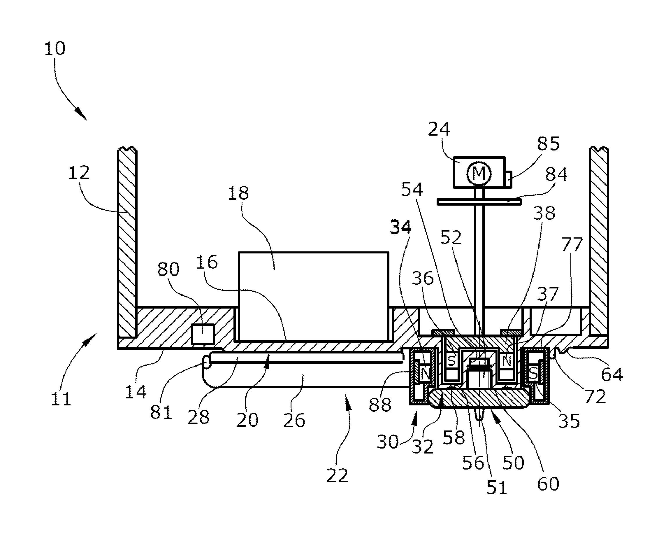
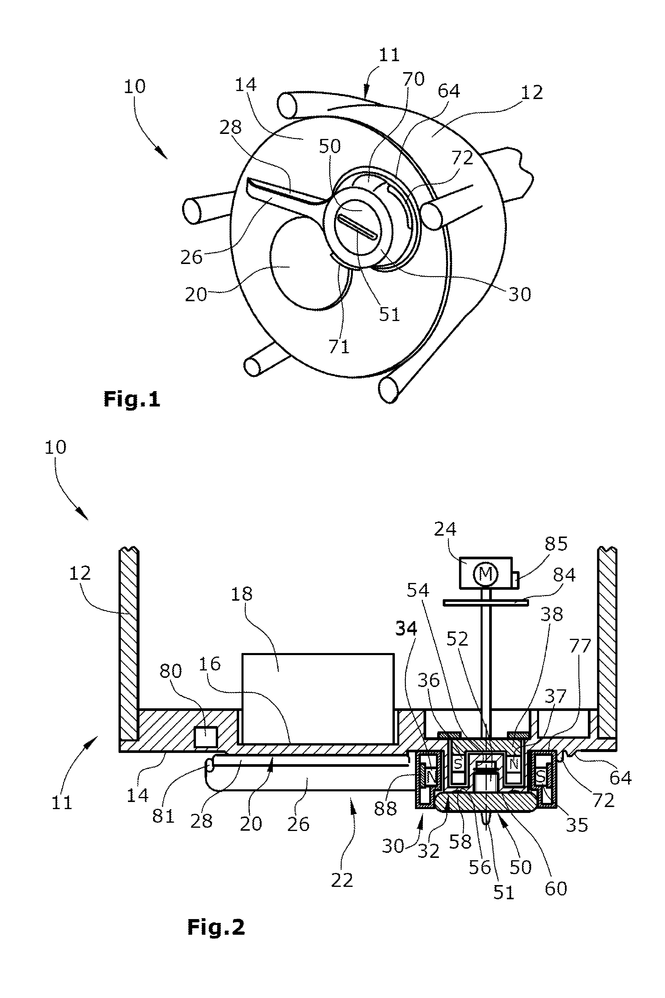
[0021]FIGS. 1 and 2 illustrate a waste water immersion probe 10 which, in the present case, is designed as an ultrasonic sludge blanket probe. The immersion probe 10 has a bipartite housing 11 formed by a pot-like housing body 12 and a circular disc-shaped housing cover 14 that forms the bottom housing wall of the housing 11. The housing body 12 is made of metal, whereas the housing cover 14 is made of plastic material. The housing body 12 and the housing cover 14 are fluid-tightly connected, e.g. screwed, glued or locked to each other. The waste water immersion probe 10 is intended for operation under permanent immersion in waste water.

[0022]On the inner side of the housing cover 14, a sensor 18 is arranged in a recess 16, which is designed as an ultrasonic sensor. The bottom of the recess 16 forms a sensor window 20 thin enough for the ultrasonic waves emitted and received by the ultrasonic sensor 18 to pass through in both directions substantially unimpeded.

[0023]The ultrasonic s...


PUM

PropertyMeasurementUnit
magnetic fieldaaaaaaaaaa
wiping movementaaaaaaaaaa
turbidityaaaaaaaaaa

Abstract

The invention relates to a waste water immersion probe (10) comprising a liquid-tight housing (11), a sensor (18) which is disposed in the housing (11) and a sensor window (20) formed on the housing (11). A wiper element (22) for cleaning the sensor window (20) is arranged on the outside of the sensor window (20), and the wiper element (22) is driven by a drive motor (24) which is arranged essentially in the housing (11). The housing is devoid of openings. A magnetic element (36, 37) is associated with the drive motor (24) and a magnetic element (34, 35) is associated with the wiper element (22) in such a manner that the magnetic drive motor element (36, 37) produces a magnetic field which transverses the housing wall and transmits a drive torque to the wiper element (22) without a shaft.

Description

[0001]This is a National Phase Application in the United States of Application No. PCT / EP2007 / 050417 filed Jan. 16, 2007, which claims priority on European Patent Application No. 06101329.8, filed Feb. 6, 2006. The entire disclosures of the above patent applications are hereby incorporated by reference.TECHNICAL FIELD[0002]The invention is directed to a waste water immersion probe comprising a liquid-tight housing with a sensor window and a wiper for cleaning the sensor window on the outer side.BACKGROUND OF THE INVENTION[0003]Waste water immersion probes are used for the detection of various parameters in waste water. Examples of these probes are turbidity sensors or solid matter sensors, ultrasonic sludge blanket probes, UV or nitrate probe, etc. In each of these immersion probes, a sensor is arranged in the housing that, through a sensor window in or at the housing, measures one of the mentioned parameters in the waste water outside the housing. Accretions on the outside of the s...

Claims


Application Information

Patent Timeline
Patent Type & Authority Patents(United States)
IPC IPC(8): G01N29/00G01N33/18
CPCG01N29/032G01N29/222G01N33/1886G01N2291/044G02B27/0006
Inventor BATTEFELD, MANFREDJONAK, ANDREASHEIDEMANNS, LOTHARLEYER, AXELSCHUSTER, MICHAEL
Owner HACH LANGE HACH LANGE
Why Eureka
Try Eureka