Thermal control system for a light-emitting diode fixture

a technology of light-emitting diodes and control systems, which is applied in the direction of lighting and heating apparatus, electric apparatus casings/cabinets/drawers, instruments, etc., can solve the problems of thermal stress of light-emitting diodes, increase in the temperature of light-emitting diodes, and additional heating of pn junctions, so as to reduce the number of component parts

Inactive Publication Date: 2011-12-06
MP DESIGN
View PDF26 Cites 33 Cited by
  • Summary
  • Abstract
  • Description
  • Claims
  • Application Information

AI Technical Summary

Benefits of technology

[0009]In particular, it is an object of the present invention to provide a thermal control system for a light-emitting diode fixture which has a reduced number of component parts.

Problems solved by technology

A significant portion of the electrical energy is converted to thermal energy which results in an increase in the temperature of the light-emitting diode.
The increased current causes additional heating of the PN junction and may thermally stress the light-emitting diode.
Thermally stressed light-emitting diodes lose efficiency and their output is diminished.
Thermally stressed light-emitting diodes may also impose an increased load on related driver components causing their temperature to increase as well.
This may result in broken wire bonds, delaminating, internal solder joint detachment, damage to die-bond epoxy, and lens yellowing.
If nothing is done to control the increasing temperature of the light emitting diode, the PN junction may fail, possibly resulting in thermal runaway and catastrophic failure.
However, the need for a controller, typically in the form of microprocessor, increases the number of components in the thermal control system and thereby increases manufacturing costs.

Method used


Image

  • Thermal control system for a light-emitting diode fixture
  • Thermal control system for a light-emitting diode fixture
  • Thermal control system for a light-emitting diode fixture

Examples


Embodiment Construction

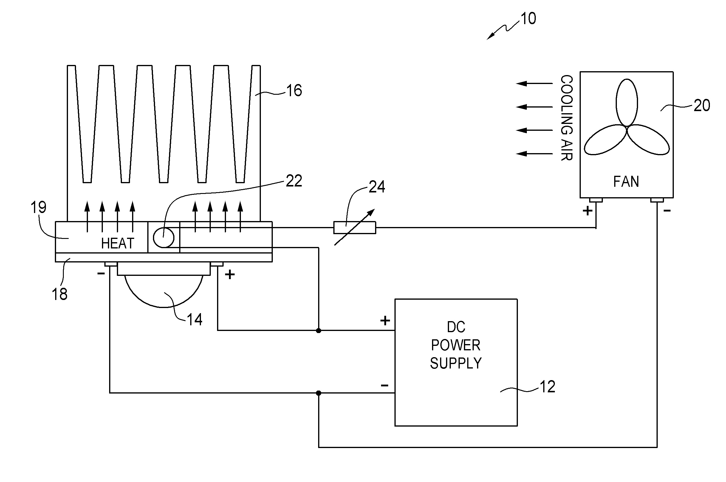
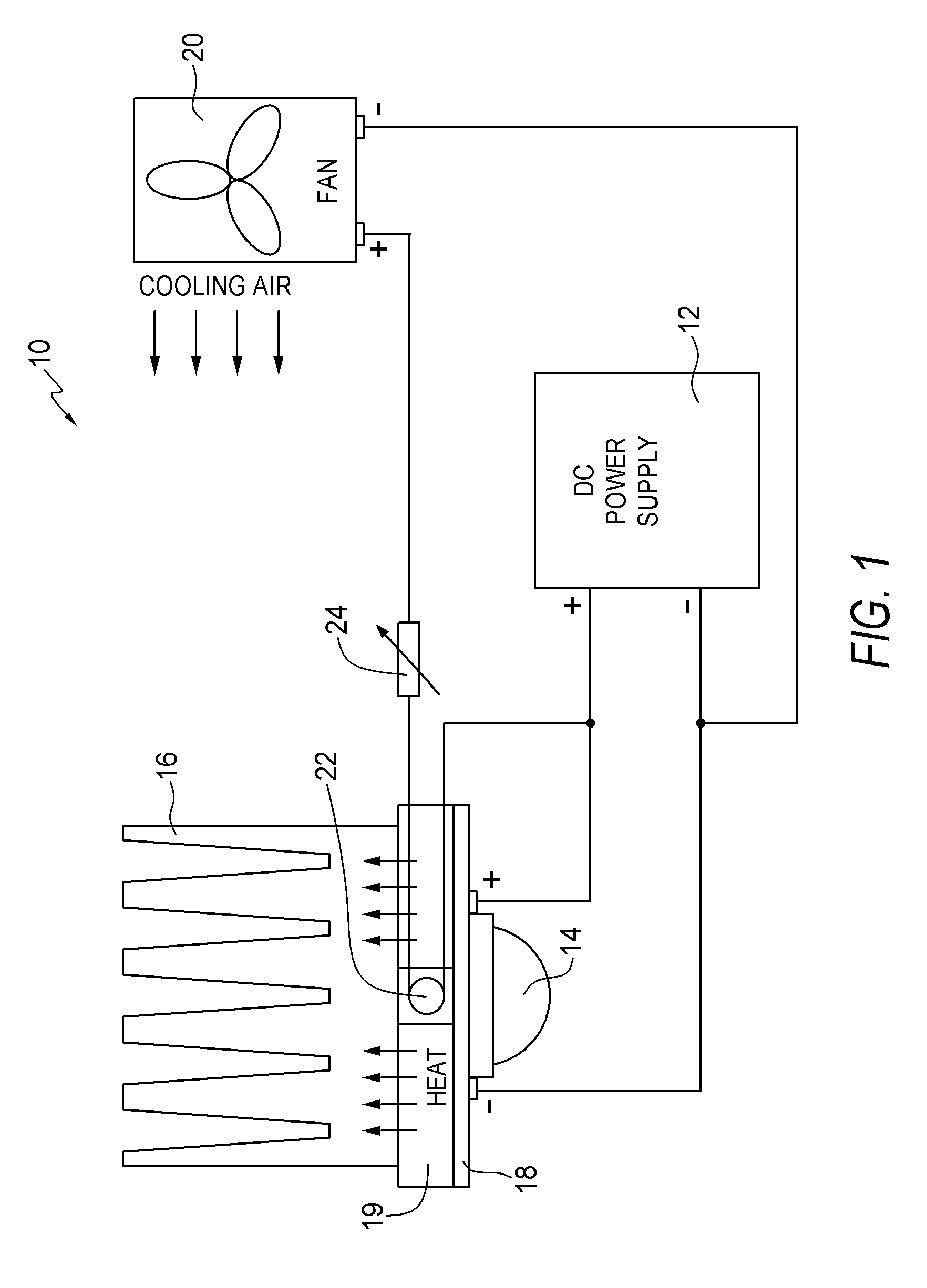
[0017]Referring first to FIG. 1, this shows a simplified block diagram of an improved thermal control system cooling system 10 for a light-emitting diode fixture 11 which is shown in FIG. 3. Referring back to FIG. 1, a DC power supply 12 is connected to a light-emitting diode 14 mounted on a printed circuit board 18. In this example, the light-emitting diode 14 and printed circuit board 18 are thermally coupled to heat sink 16 by a thermal conductive member, in this example, a metal plate 19. However, this is not a requirement. The metal plate 19, preferably formed of copper or aluminum, is disposed between the printed circuit board 18 and the heat sink 16. The power supply 12 is also connected to a cooling device which, in this example, is cooling fan 20. A thermistor 22, thermally coupled to the heat sink 16, is connected in series between the DC power supply 12 and the cooling fan 20. Preferably the thermistor 22 is disposed within, or nested in, the metal plate 19. A resistor, i...


PUM


Abstract

A thermal control system for a light-emitting diode comprises a thermistor array thermally coupled to a heat sink. The thermistor array may be disposed within a thermal conductive member. A power supply is electrically connected to the thermistor array. A cooling device is electrically connected in series with the power supply and the thermistor array. The thermistor array is between the power supply and the cooling device. A rheostat may further be electrically connected, in series, between the thermistor array and the cooling device.

Description

BACKGROUND OF THE INVENTION[0001]1. Field of the Invention[0002]The present invention relates to light-emitting diodes and, in particular, to a thermal control system for a light-emitting diode fixture.[0003]2. Description of the Related Art[0004]Light-emitting diodes, like any semiconductor, emit heat during their operation. This is because not all of the electrical energy provided to a light-emitting diode is converted to luminous energy. A significant portion of the electrical energy is converted to thermal energy which results in an increase in the temperature of the light-emitting diode. In resistor driven circuits, as the temperature of the light-emitting diode increases, the forward voltage drops and the current passing through the PN junction of the light-emitting diode increases. The increased current causes additional heating of the PN junction and may thermally stress the light-emitting diode.[0005]Thermally stressed light-emitting diodes lose efficiency and their output ...

Claims


Application Information

Patent Timeline
Patent Type & Authority Patents(United States)
IPC IPC(8): F21V29/00H05B44/00
CPCF21V29/02G05D23/24F21V29/80H05B33/0803F21Y2101/02H01L2924/0002H01L2924/00F21Y2115/10F21V29/67F21Y2105/10F21V29/61F21V29/74H05B45/30
Inventor KORNITZ, ALEXANDERPOSPISIL, MIREK
Owner MP DESIGN
Why Eureka
Try Eureka