
Teeth separating apparatus

a technology of separating apparatus and stainless steel, which is applied in the field of teeth separating apparatus, can solve the problems of abrasive stainless strips having sharp edges, affecting the quality of teeth, and requiring great precision, and can not be easily manufactured and sterilized, etc., to achieve the effect of convenient use, durable and reliable use, and convenient us

Active Publication Date: 2011-12-06
ZEST IP HLDG
View PDF47 Cites 62 Cited by
  • Summary
  • Abstract
  • Description
  • Claims
  • Application Information

AI Technical Summary

Benefits of technology

[0021]In addition, a novel saw is revealed in the present application for use with the apparatus for separating teeth, above described. The saw includes a plate having a first side and second side with a perimetric edge between the first and second sides. An abrasive application, such as diamond particles, may form an abrasive surface on the first side of the plate. The second side of the plate is necessarily void of any abrasive material. The shaft connects to the plate and is reciprocated by the use of known reciprocating dental tools. The shaft of the saw may be easily rotated 180 degrees to allow the abrasive side of the plate to remove the enamel from adjacent teeth, seriatum.
[0023]It is therefore an object of the present invention to provide an apparatus for separating a pair of teeth which is easy to use by a dental practitioner in performing inter-proximal reduction of enamel procedures.
[0024]Another object of the present invention is to provide an apparatus for separating a pair of adjacent teeth which is durable and reliable in its use.
[0025]A further object of the present invention is to provide an apparatus for separating a pair of teeth which includes protection for the papilla, tongue, and lip of the patient when cutting tools are employed to perform slenderizing procedures.
[0026]A further object of the present invention is to provide a tooth separator for a pair of adjacent teeth which is formed in one piece and is easily manufactured and sterilized.
[0027]Another object of the present invention is to provide a cutting tool for removing enamel in conjunction with a tooth separator that may be easily and efficiently employed to perform inter-proximal enamel reductions.

Problems solved by technology

Unfortunately, such techniques require great precision and damage to the tongue, teeth, and lips must be avoided.
Wooden wedges induce pain in patients and often cause gingival papillae bleeding, which can confound later adhesive bonding.
Moreover, the abrasive stainless strips possess sharp edges and are prone to fracture, such fracturing has caused lacerations on the lips, gingival papillae, floor of the mouth and tongue, since these areas are unprotected.
Screw driven separators may also exert excessive forces on the teeth crowns and roots, resulting in fractures in the enamel and dentine.

Method used


Image

  • Teeth separating apparatus
  • Teeth separating apparatus
  • Teeth separating apparatus

Examples


Embodiment Construction

[0038]Various aspects of the present invention will evolve from the following detailed description of the preferred embodiments thereof which should be referenced to the prior described drawings.

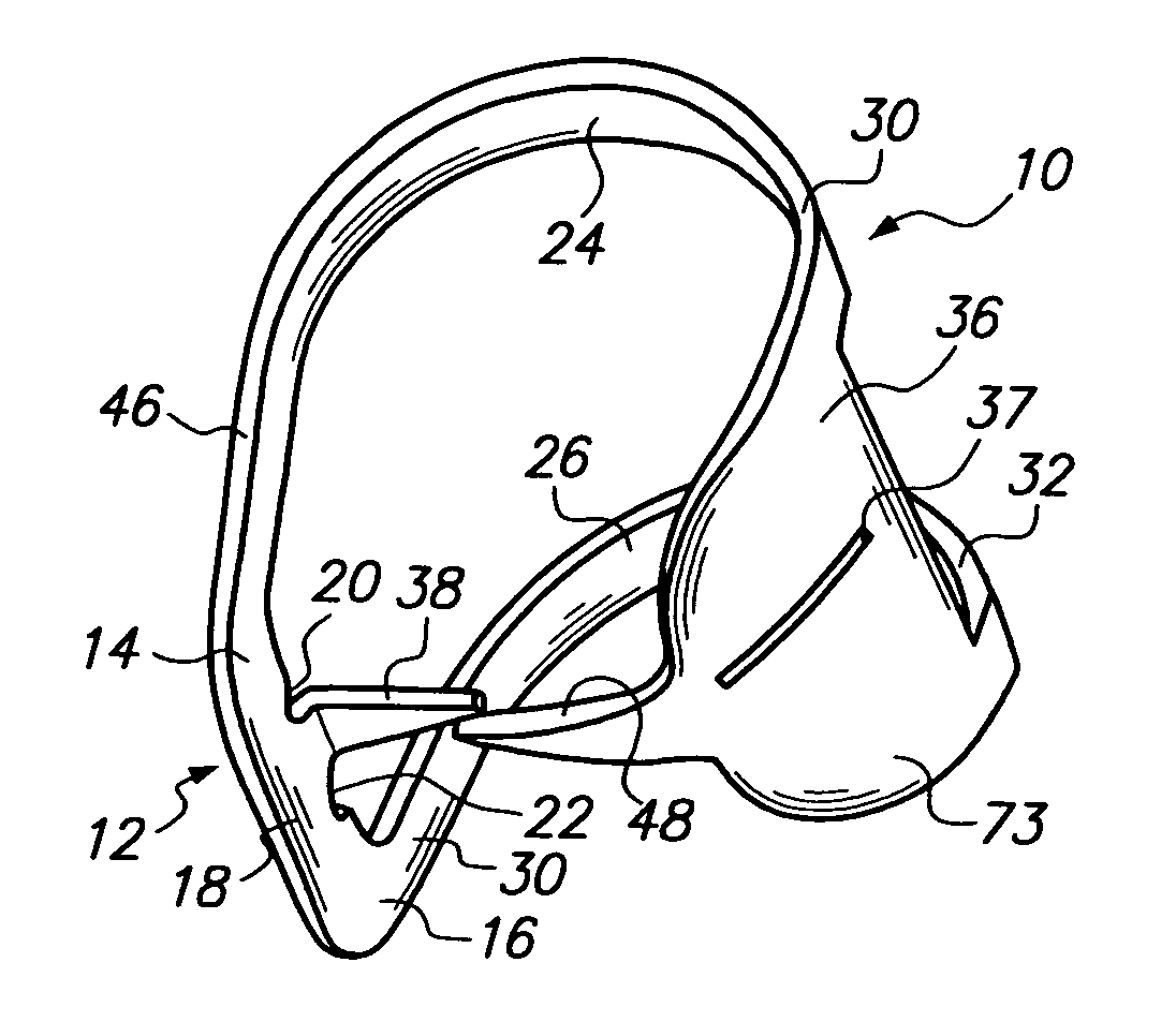
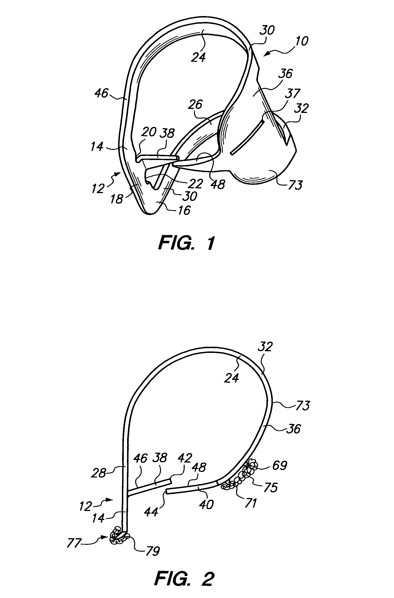
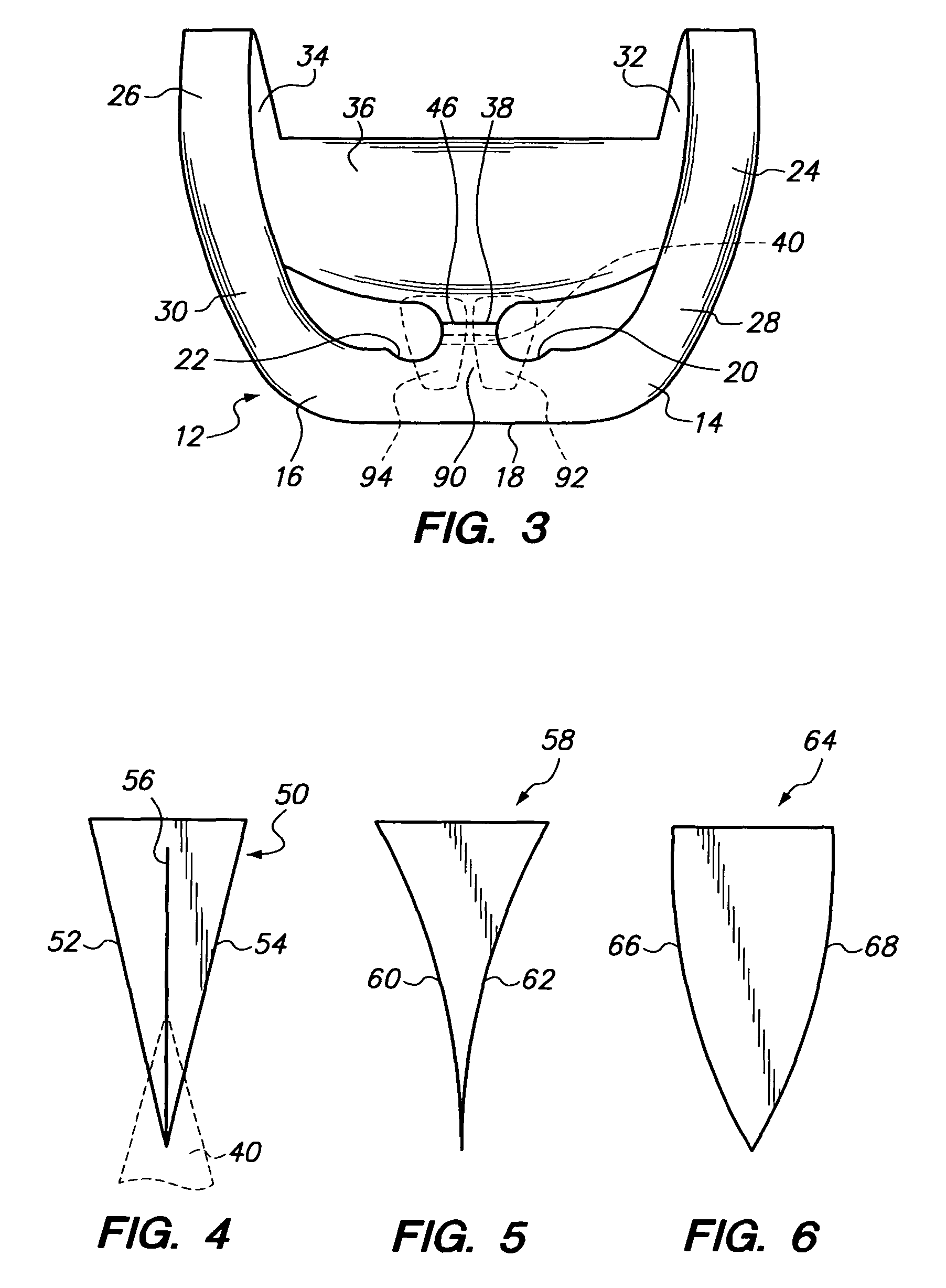
[0039]The tooth separating apparatus of the present invention is depicted in an embodiment 10 depicted in FIGS. 1-3 and 8. Apparatus 10 includes as one of its elements a base member 12. Base member 12 is formed with a first end portion 14, a second end portion 16, and an intermediate portion 18 interconnecting first and second end portions 14 and 16, respectively. Base member 12 also includes notches 20 and 22 which are used to support other dental devices such as a rubber dam forceps or pliers. Base member 12 as well as the remaining portions of apparatus 10, which will be described hereinafter, may be formed of any resilient material such as metal. In particular, 400 series stainless steel suffices in this regard.

[0040]First spring 24 and second spring 26 extend from first end portion 14 a...


PUM


Abstract

An apparatus for separating teeth utilizing a base member having a first end portion, a second end portion, and an intermediate portion. A first spring extends outwardly from the first end portion while a second spring extends outwardly from the second portion of the base member. A lingual shield spans the distal portions of the first and second springs extending from the base member. A pair of tines overlap one another, one tine extending from the base member, the other extending from the shield. The first and second springs urge the meeting or overlapping of the first and second tines in the vicinity of gap for meeting place between a pair of teeth.

Description

BACKGROUND OF THE INVENTION[0001]The present invention relates to a novel and useful apparatus for separating a pair of adjacent teeth.[0002]Malocclusions are treated by orthodontists using various mechanical and chemical techniques. Prior to the implementation of such techniques, teeth-size modification must take place to correct crowding of teeth adjacent to one another. In the past, such teeth crowding had been corrected by teeth extractions or moving teeth into unstable or unrealistic positions.[0003]The current procedures for the modeling of teeth is often is referred to as “slenderizing” or inter-proximal reduction of enamel. To achieve this result, the practitioner must first separated adjacent teeth and remove enamel with a mechanical device with a saw or rasp. Unfortunately, such techniques require great precision and damage to the tongue, teeth, and lips must be avoided.[0004]Specifically prior methods require the use of wooden wedges to allow the employment of very thin s...

Claims


Application Information

Patent Timeline
IPC IPC(8): A61C3/12A61C5/12A61C15/00
CPCA61C5/125A61C5/85
Inventor ROETZER, PATRICK L.BRUNS, CRAIG
Owner ZEST IP HLDG
Learn More