System and method for improving the efficiency of routers on the internet and/or cellular networks and/or other networks and alleviating bottlenecks and overloads on the network

a router and network efficiency technology, applied in the field of router optimization on the internet, can solve the problems of crude response time of optical switches and less efficient, and achieve the effects of convenient and cheaper, efficient buffering, and simple and flexible buffering

Inactive Publication Date: 2011-12-06
BARHON MAYER BATYA
View PDF12 Cites 42 Cited by
  • Summary
  • Abstract
  • Description
  • Claims
  • Application Information

AI Technical Summary

Benefits of technology

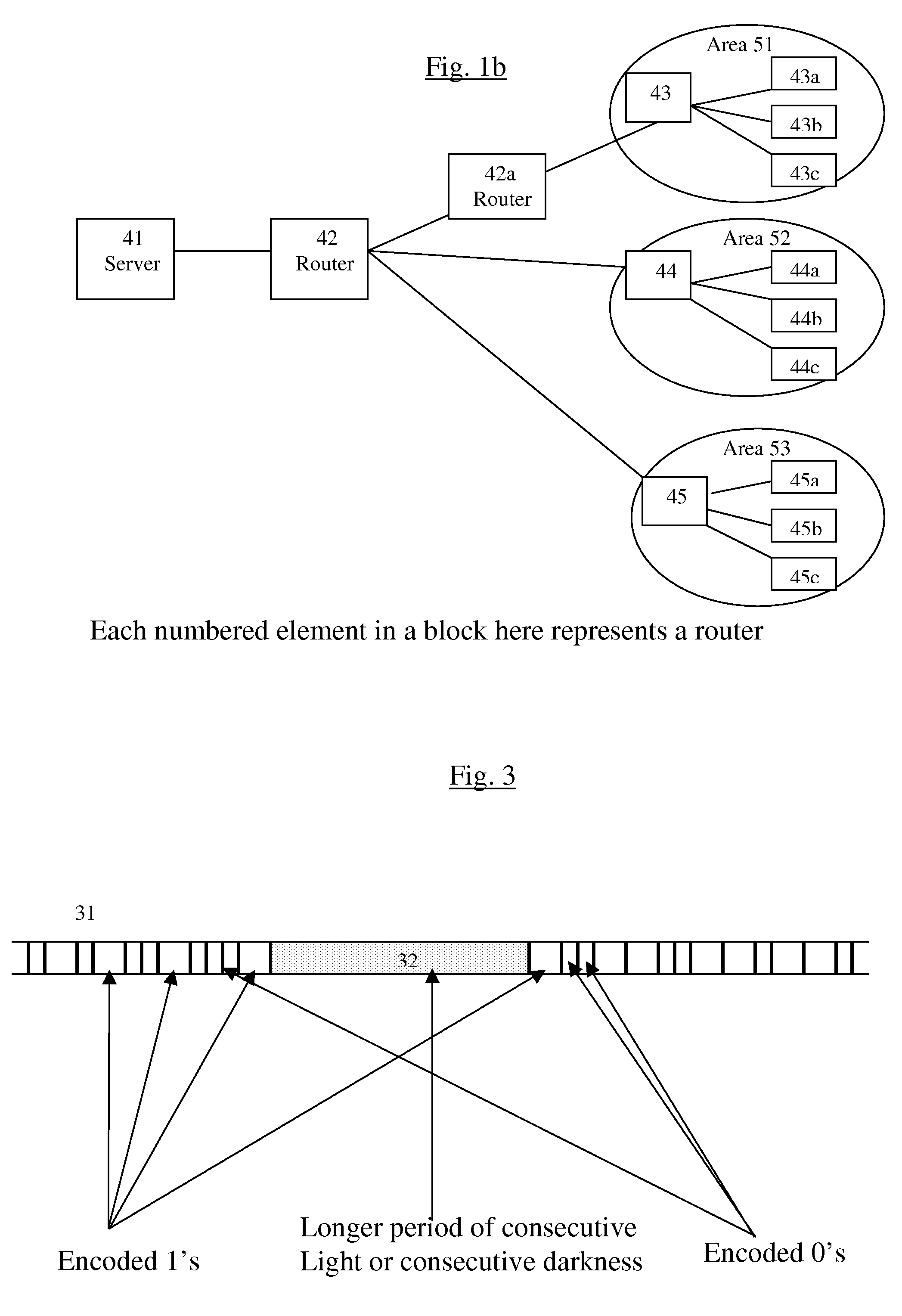
[0027]Another optimization described in this invention in another possible variation, which is related to the efficient handling of the packets by the routers, is improving routing efficiency and bandwidth utilization efficiency in Networks of interconnected devices such as for example the Internet and cellular networks, by using much more efficiently physical addresses and / or by grouping together identical data packets from the same source going to the same general area so that the body of the packet is sent only once with a multiple list of targets attached to it, to each general target area. This grouping is preferably done by the server of the originating source itself, and is preferably based a physical addresses system, such as for example GPS. These grouped packets are then preferably broken down into smaller groups by the routers in the general target area and finally broken down to individual data packets for delivering to the final actual destinations. This saves both bandwidth and the number of routing decisions needed on the way, since only a single copy of the identical data is sent in each group, and this is why this can be called condensed packets. Another possible variation is that preferably the server can also group together non-identical packets (such as for example packets from different files or a number of different condensed packets of the type described above) going in the same general area, with a combined header or general area tag, although in this case the different packets or groups of condensed packets can not be further condensed to a single copy of the data, so the saving is only on the number of headers that need to be processed along the way for making routing decisions. Such groups of different packets going in the same direction are also then preferably similarly broken down into smaller groups by the routers in the general target area and finally broken down to individual data packets for delivering to the final actual destinations. These optimizations can be very useful for example for optimizing the access to very popular sites such as for example Yahoo or CNN, and can be used also for example for more efficiently transferring streaming data, such as for example from Internet radio stations, or even for example Internet TV stations which will probably exist in the next years, a thing which ordinary proxies cannot do. This can work even more efficiently when it is applied in addition to the current state of the art load distribution systems, such as for example Akamai. The combinations of using both the various physical address optimizations and the separate handling of headers can of course further enhance each other. This is explained in more detail as part of the reference to FIG. 1b.
[0029]1. Non-blocking packet switching in Optical Routers, by dealing much more efficiently only with the headers, without having to convert the packets to electronics and back, while solving all the relevant problems.
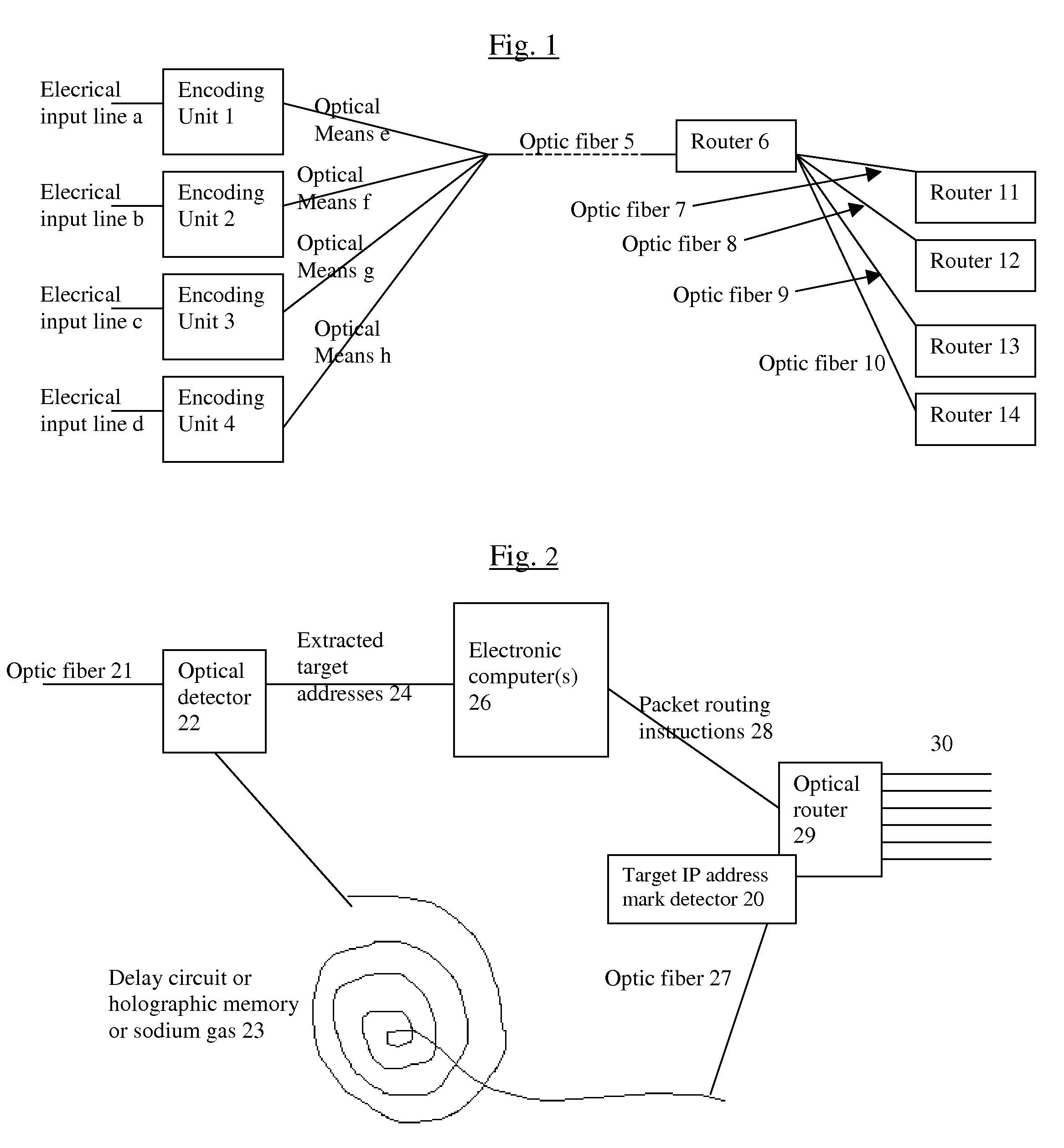
[0030]2. New architecture and principles for routing based on physical geographical IP addresses (such as for example based on GPS), in a way much more efficient than has been previously discussed in the literature that suggested using physical (geographical) addresses. This is preferably based on a hierarchical infrastructure of routers—in a way similar to a hierarchical road system, so that routers that are higher in the hierarchy preferably have direct broadband connections with their peers (and preferably also direct links to farther peers), so that they don't have to go through lower level routers to reach their peers. However, conversion from the current architecture to the new one can be done very easy, as shown in the description below.
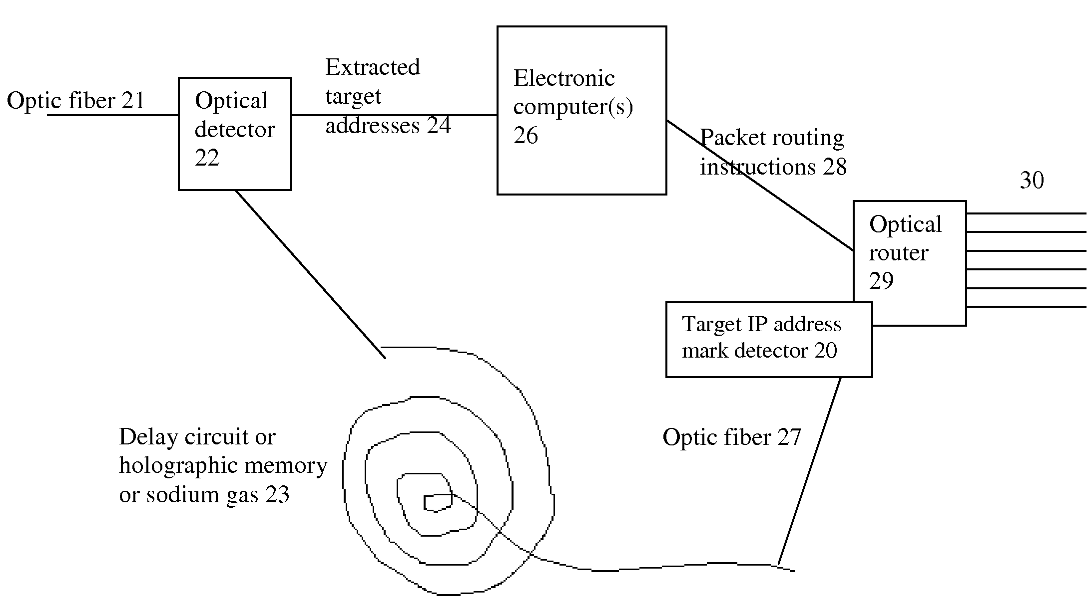
[0036]4. Solution number 4 does not use any change in color (wavelength) for marking the target addresses (and / or the packet headers or the beginnings of them), but instead uses a temporal method of marking it, which is much cheaper and easier to create and also easier to detect later. Preferably, this can be easily done by simply marking the position of the target IP address with a period of no light considerably longer than ordinary. Preferably, This considerably longer period is at the beginning of the packet and the exact position of the target IP address is defined by a slight shift from there or marked separately.
[0040]8. Solution number 8 is using for the mark a temporally different kind of bits, for example fatter bits. So, for example, if normal 1's are 20 picometers wide and 0's are 10 picometers wide, the marks can use for example 1's that are 60 picometers wide and 0's that are 30 picometers wide. The proportional change of 0's and 1's does not have to be the same, and also the width of the separator between bits can be either also changed or not changed. (Of course this is just an example and 0's can be for example the same temporal width as 1's but identified by different light intensity levels, etc.) This solution is in a way a combination of solutions 4 and 5 and it is better than them because it enables the mark to carry also information, and also avoids problems such as a dark mark being the same as a period of a silence in transmission. This mark of fat bits can be for example in front of the packet header, but preferably the entire packet header itself or at least parts of it (such as for example the target address) are encoded or duplicated in fat bits. This enables easier handling of the header even if the bit stream is extremely fast. Of course various combinations of the solutions are also possible, such as for example a longer consecutive period of darkness or light before the beginning of the fat bits of the header.

Problems solved by technology

(In case this distance can change, marking may be done for example for both the beginning of the packet and the position of the target IP address, or some more bits have to be read for finding the exact second position, but this is less efficient.
Another problem is the crudeness of the response time of the optical switch as explained above.

Method used


Image

  • System and method for improving the efficiency of routers on the internet and/or cellular networks and/or other networks and alleviating bottlenecks and overloads on the network
  • System and method for improving the efficiency of routers on the internet and/or cellular networks and/or other networks and alleviating bottlenecks and overloads on the network
  • System and method for improving the efficiency of routers on the internet and/or cellular networks and/or other networks and alleviating bottlenecks and overloads on the network

Examples


Embodiment Construction

[0048]All of the descriptions in this and other sections are intended to be illustrative examples and not limiting.

[0049]Referring to FIG. 1, we are assuming for the simplicity and clarity of the example, that there are only 4 lambdas carried simultaneously by the optic fiber. So there are 4 units (marked 1-4) that encode electrical bits from electrical input lines (marked a-d) respectively into the light bits of each lambda, and while encoding them, these units preferably find the target address of each data packet and / or the beginning of the packet header and mark them with an optically obtrusive mark, or mark the entire header, so that the computer that makes the packet switching decisions will get the entire header. Preferably the target address is very close to the beginning of the packet and at a constant distance from it, so only one mark is needed for each packet. Most preferably the target address would be the first thing at the beginning of the header. Unfortunately, accor...


PUM


Abstract

Optical routers are currently unable to do packet switching except by translating the data to electronic data and then back, which is very inefficient. The present invention solves this problem by optically marking and detecting the packet headers or parts of them, translating at most only the headers or parts of them to electronics for making packet switching decisions, and keeping the rest of the packets in optical delay lines, and solving response-time problems. Another optimization described in this invention is improving routing efficiency and bandwidth utilization by grouping together identical data packets from the same source going to the same general area with a multiple list of targets connected to each copy of the data and sent together to the general target area. Another important optimization is a new architecture and principles for routing based on physical geographical IP addresses.

Description

[0001]This patent application is a Continuation-In-Part of U.S. patent application Ser. No. 10 / 375,208 of Feb. 17, 2003, which is a CIP of U.S. application Ser. No. 10 / 328,622 of Dec. 26, 2002, hereby incorporated by reference in their entireties, which are a Continuation-In-Part of PCT / IL 01 / 01042 (which was filed in Israel on Nov. 8, 2001, hereby incorporated by reference in its entirety, which claims priority from Israeli patent application 139559 of Nov. 8, 2000 and from U.S. provisional patent application 60 / 266,730 of Feb. 5, 2001, and from U.S. provisional patent application 60 / 299,919 of Jun. 19, 2001, hereby incorporated by reference in their entireties) and which also claim benefit and priorities from the following US Provisional patent applications, hereby incorporated by reference in their entireties:[0002]60 / 344,455 of Dec. 26, 2001[0003]60 / 344,652 of Dec. 28, 2001[0004]60 / 353,781 of Jan. 29, 2002[0005]60 / 356,554 of Feb. 10, 2002[0006]60 / 358,231 of Feb. 14, 2002[0007]60...

Claims


Application Information

Patent Timeline
Patent Type & Authority Patents(United States)
IPC IPC(8): H04J14/08H04J3/26H04L12/00H04J14/02
CPCH04J14/0227H04Q11/0005H04J14/0232H04J14/0238H04Q2011/0039H04J14/0282H04J14/0284H04Q11/0066H04Q2011/002
Inventor MAYER, YARONBAUR, AL J. C.
Owner BARHON MAYER BATYA
Why Eureka
Try Eureka