System and method for improving the efficiency of routers on the Internet and/or cellular networks and/or other networks and alleviating bottlenecks and overloads on the network

a router and network efficiency technology, applied in the field of router optimization on the internet, can solve the problems of crude response time of optical switches and less efficient, and achieve the effects of convenient and cheaper buffering, convenient and convenient use, and efficient operation

Inactive Publication Date: 2008-06-19
BARHON MAYER BATYA
View PDF12 Cites 51 Cited by
  • Summary
  • Abstract
  • Description
  • Claims
  • Application Information

AI Technical Summary

Benefits of technology

[0008]The present invention solves the above problems by working around the synchronization problem, so that the system is able to automatically compensate for the crudeness of the response time of the optical switch (at least a few nanoseconds with the available optical switches described above) compared to the speed of the bits flow. This way the “cutting knife” can be much thicker than the point it has to cut between each two consecutive packets. Obviating the need for synchronization between packets also enables simpler and more flexible buffering, so that the delay lines can even deal with packets of sizes longer than the lengths of the delay lines. The routers read only the headers or parts of them by optically preferably obtrusively marking the target IP addresses or the entire headers or parts of them, or optically preferably obtrusively marking the beginning of each packet header and preferably making sure that the distance in bits between the beginning of the packet and the position of the target IP address is always constant, or marking both. Since the position of the target IP address in the TCP/IP protocol is close to the position of beginning of the packet, it is very easy to find both positions when at least one of them is marked. (In case this distance can change, marking may be done for example for both the beginning of the packet and the position of the target IP address, or some more bits have to be read for finding the exact second position, but this is less efficient. Keeping this distance constant and keeping both positions close to each other is more preferable). So from now on, throughout the text of the patent, including the claims, marking the target IP address means either marking the target address itself directly or marking it indirectly by marking the beginning of the packet header, or marking both, or marking the entire header or part of it, so that in any case this marking also enables us to know the position of the beginning of the packet (See also the glossary for more clarification). If both are marked, the 2 kinds o...

Problems solved by technology

(In case this distance can change, marking may be done for example for both the beginning of the packet and the position of the target IP address, or some more bits hav...

Method used


Image

  • System and method for improving the efficiency of routers on the Internet and/or cellular networks and/or other networks and alleviating bottlenecks and overloads on the network
  • System and method for improving the efficiency of routers on the Internet and/or cellular networks and/or other networks and alleviating bottlenecks and overloads on the network
  • System and method for improving the efficiency of routers on the Internet and/or cellular networks and/or other networks and alleviating bottlenecks and overloads on the network

Examples


Embodiment Construction

[0031]All of the descriptions in this and other sections are intended to be illustrative examples and not limiting.

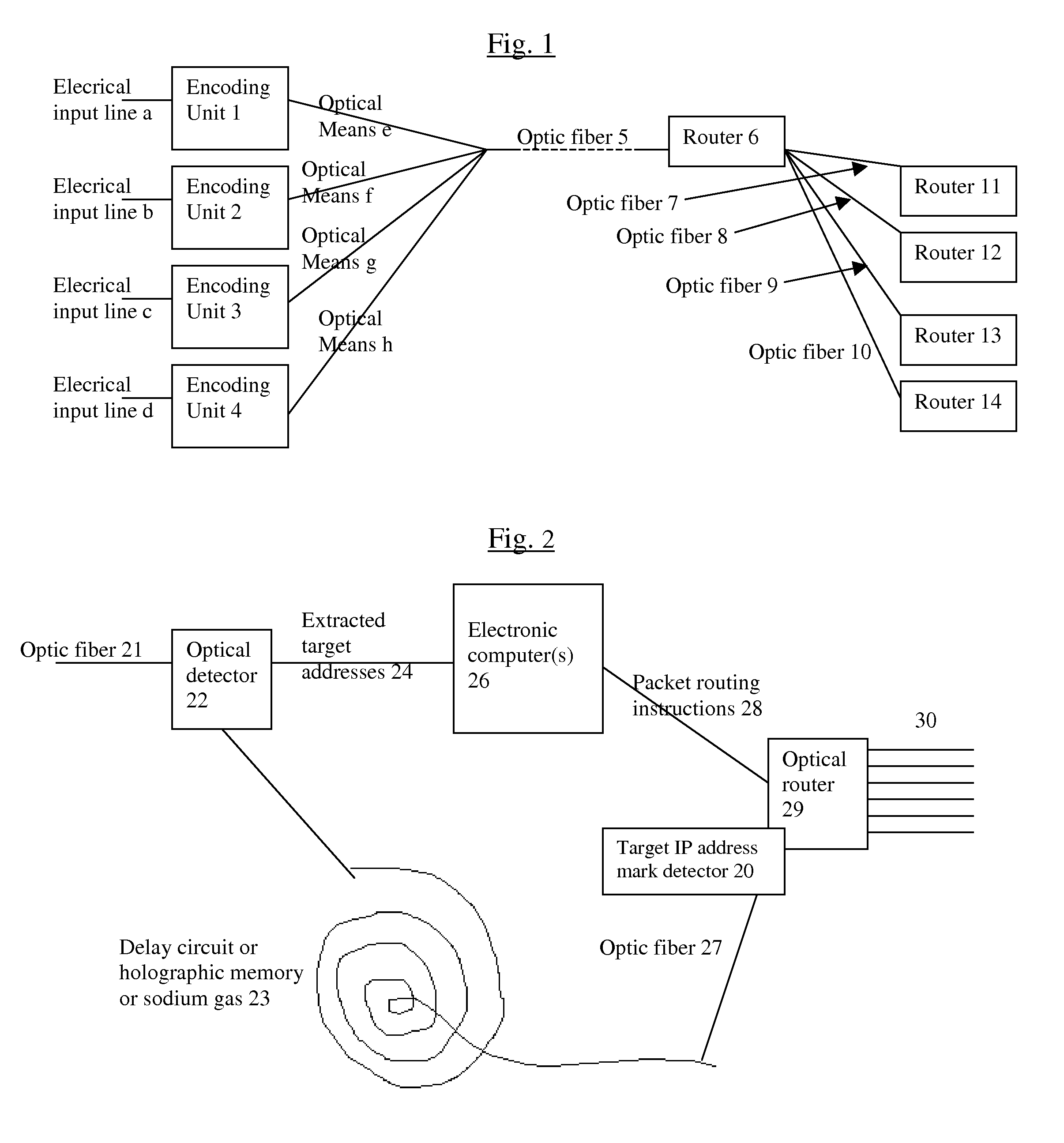
[0032]Referring to FIG. 1, we are assuming for the simplicity and clarity of the example, that there are only 4 lambdas carried simultaneously by the optic fiber. So there are 4 units (marked 1-4) that encode electrical bits from electrical input lines (marked a-d) respectively into the light bits of each lambda, and while encoding them, these units preferably find the target address of each data packet and / or the beginning of the packet header and mark them with an optically obtrusive mark, or mark the entire header, so that the computer that makes the packet switching decisions will get the entire header. Preferably the target address is very close to the beginning of the packet and at a constant distance from it, so only one mark is needed for each packet. Most preferably the target address would be the first thing at the beginning of the header. Unfortunately, accor...


PUM


Abstract

The biggest bottleneck in the Internet today is caused by the slow speed of routers, compared to the speeds that are achieved by optic fibers with DWDM (Dense Wave Division Multiplexing). Packet switching or something similar to it is needed not just for better utilization of the lines, but also because it is superior to circuit switching in many ways, such as better scalability as the Internet grows, better handling of traffic congestions, and better routing flexibility. But optical routers are currently unable to do packet switching except by translating the data to electronic data and then back, which is very inefficient. The present invention solves this problem by optically marking and detecting the packet headers or parts of them, translating at most only the headers or parts of them to electronics for making packet switching decisions, and keeping the rest of the packets in optical delay lines, and solving response-time problems in the router, so that the crude optical switches can execute the packet switching decisions at fast bit rates. This solution has very high scalability and becomes even more efficient when physical addresses are used. Another optimization described in this invention is improving routing efficiency and bandwidth utilization by grouping together identical data packets from the same source going to the same general area with a multiple list of targets connected to each copy of the data and sent together to the general target area. These grouped packets are then preferably broken down into smaller groups by the routers in the general target area and finally broken down to individual data packets for delivering to the final actual destinations. This optimization works best with Physical addresses, and can be very useful for example for optimizing the access to very popular sites such as for example Yahoo or CNN, and can be used also for example for more efficiently transferring streaming data, such as for example from Internet radio stations, or Internet TV stations which will probably exist in the next years. Another important optimization is a new architecture and principles for routing based on physical geographical IP addresses (such as for example based on GPS), in a way much more efficient than has been previously discussed in the literature that suggested using physical (geographical) addresses. This is preferably based on a hierarchy similar to a hierarchical road system, so that preferably the MAIN routers (and/or intermediary-level routers) are preferably also connected directly and preferably with high-bandwidth as peers between each other, without having to go through lower-level routers in order to reach their peers, so that once a higher-level router (and especially if it's one of the MAIN routers) decides to forward a packet (or a group of packets) to a higher-level peer, preferably the packets don't have to go through lower level routers. However, conversion from the current architecture to the new one can be done very easy, as shown in the description below.

Description

BACKGROUND OF THE INVENTION[0001]1. Field of the Invention[0002]The present invention relates to router optimizations on the Internet, and more specifically to a system and method for improving the efficiency of routers on the Internet and / or cellular networks and / or other networks and alleviating bottlenecks and overloads on the network.[0003]2. Background[0004]With the current explosion of information transfer, optic fibers are becoming faster all the time. Most of the recent advances in the amounts of data that these fibers can carry per time unit have come from adding more and more wavelengths (termed lambdas) to the same fiber at the same time, a method which is called DWDM (Dense Wave Division Multiplexing). The biggest obstacle to this was the lack of suitable amplifiers, until the Erbium amplifiers were discovered in the late 80's, which have 2 advantages: 1. They don't need to convert the optical signals to electricity and back, but instead, light in the feeble input signal...

Claims


Application Information

Patent Timeline
IPC IPC(8): H04J14/02
CPCH04Q2011/0039H04J14/0227H04J14/0282H04J14/0284H04J14/0238H04Q11/0066H04Q2011/002H04J14/0232H04Q11/0005
Inventor MAYER, YARONBAUR, AL J.C.
Owner BARHON MAYER BATYA
Why Eureka
Try Eureka