
Actuating device

a technology of actuators and actuators, applied in the direction of power transmission/actuator features, noise prevention/rattling locking, electrical locking circuits, etc., can solve the problems of mechanical and/or electrical production friction resistance having to be overcome, increasing costs, and increasing weight, so as to minimise the idle stroke of the cam wheel and minimise the noise

Inactive Publication Date: 2005-08-02
INTIER AUTOMATIVE CLOSURES INC
View PDF17 Cites 11 Cited by
  • Summary
  • Abstract
  • Description
  • Claims
  • Application Information

AI Technical Summary

Benefits of technology

[0011]With the actuating device according to the invention it is possible to have an adjustment lever which can be both electrically driven and manually moved easily and cheaply. Compared with conventional solutions the actuating device according to the invention is characterised by reduced costs and lower weight. The actuating device according to the invention is particularly suitable for use in vehicle locks, including, for example, those which are a part of central locking systems for motor vehicles.
[0021]It has also proved advantageous to construct the cams and / or the dog with a buffer device. The use of buffer means such as rubber buffers or leaf springs minimises the noise produced when a cam meets the dog.

Problems solved by technology

However, the provision of a mechanical back-up incurs greater costs and adds weight.
In addition to this automatic movement, manual movement is also possible, the disadvantage being that mechanically and / or electrically produced frictional resistance has to be overcome on account of the electric drive.

Method used


Image

  • Actuating device
  • Actuating device
  • Actuating device

Examples


Embodiment Construction

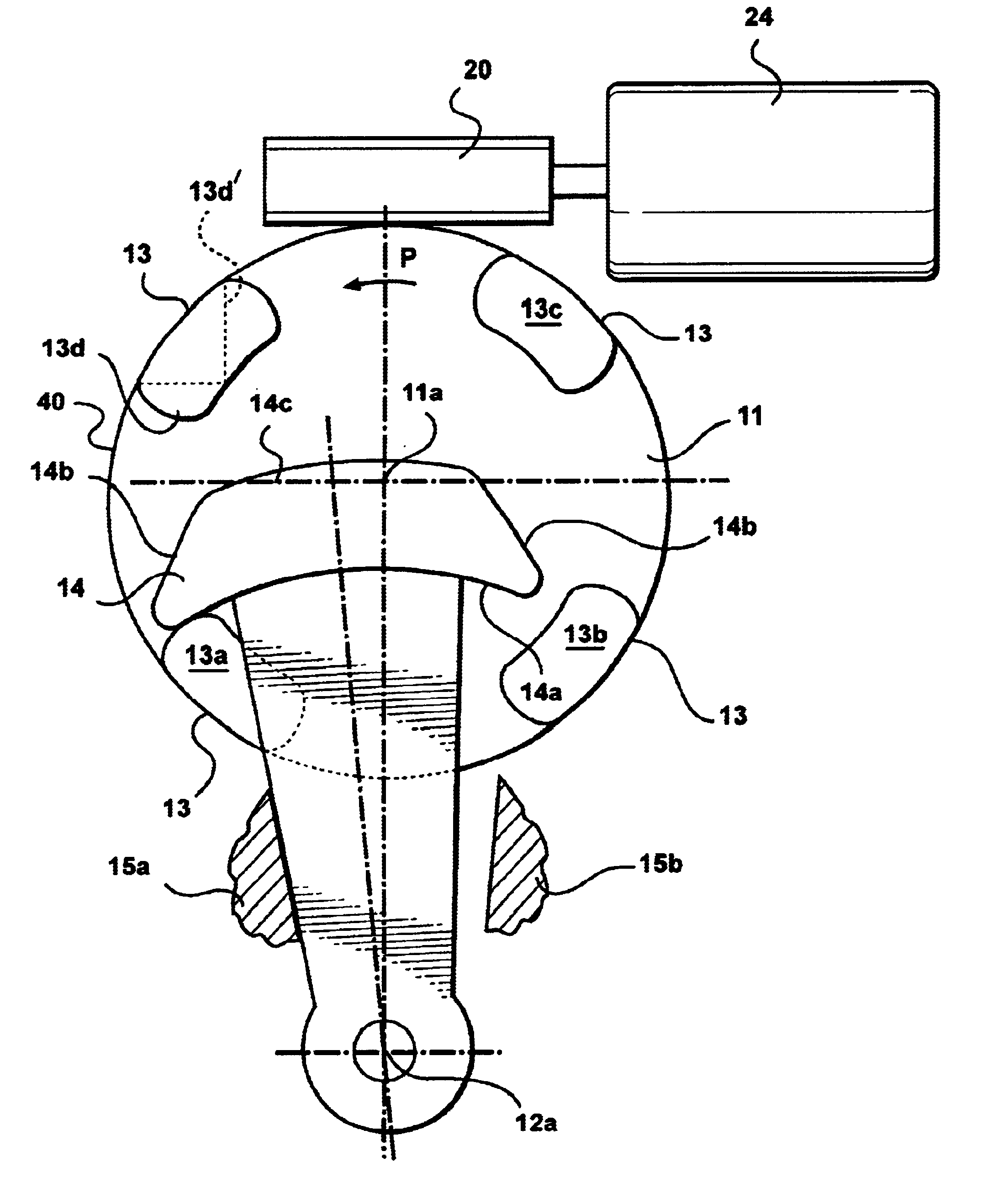
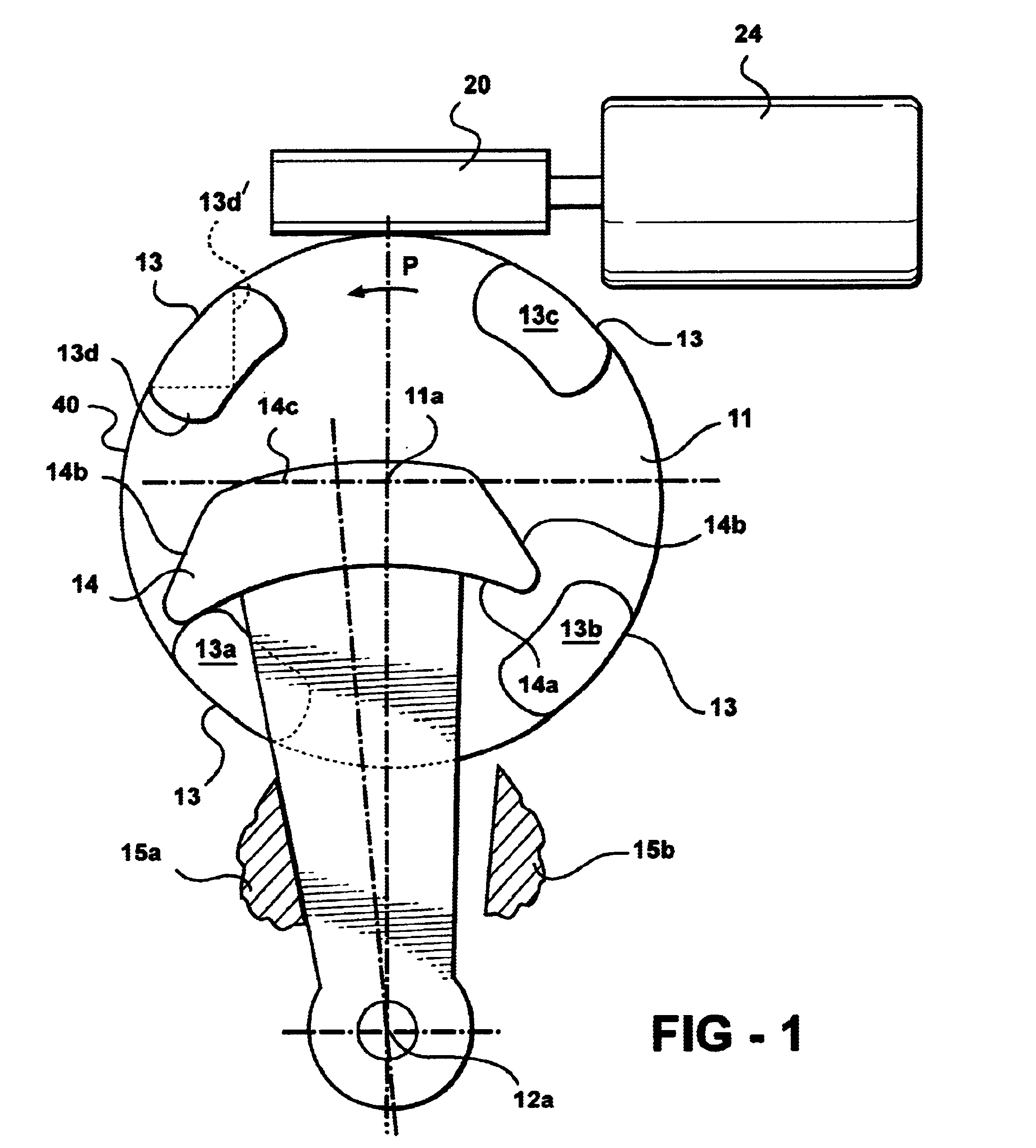
[0028]In FIG. 1 the device according to the invention is shown diagrammatically and generally designated 10.

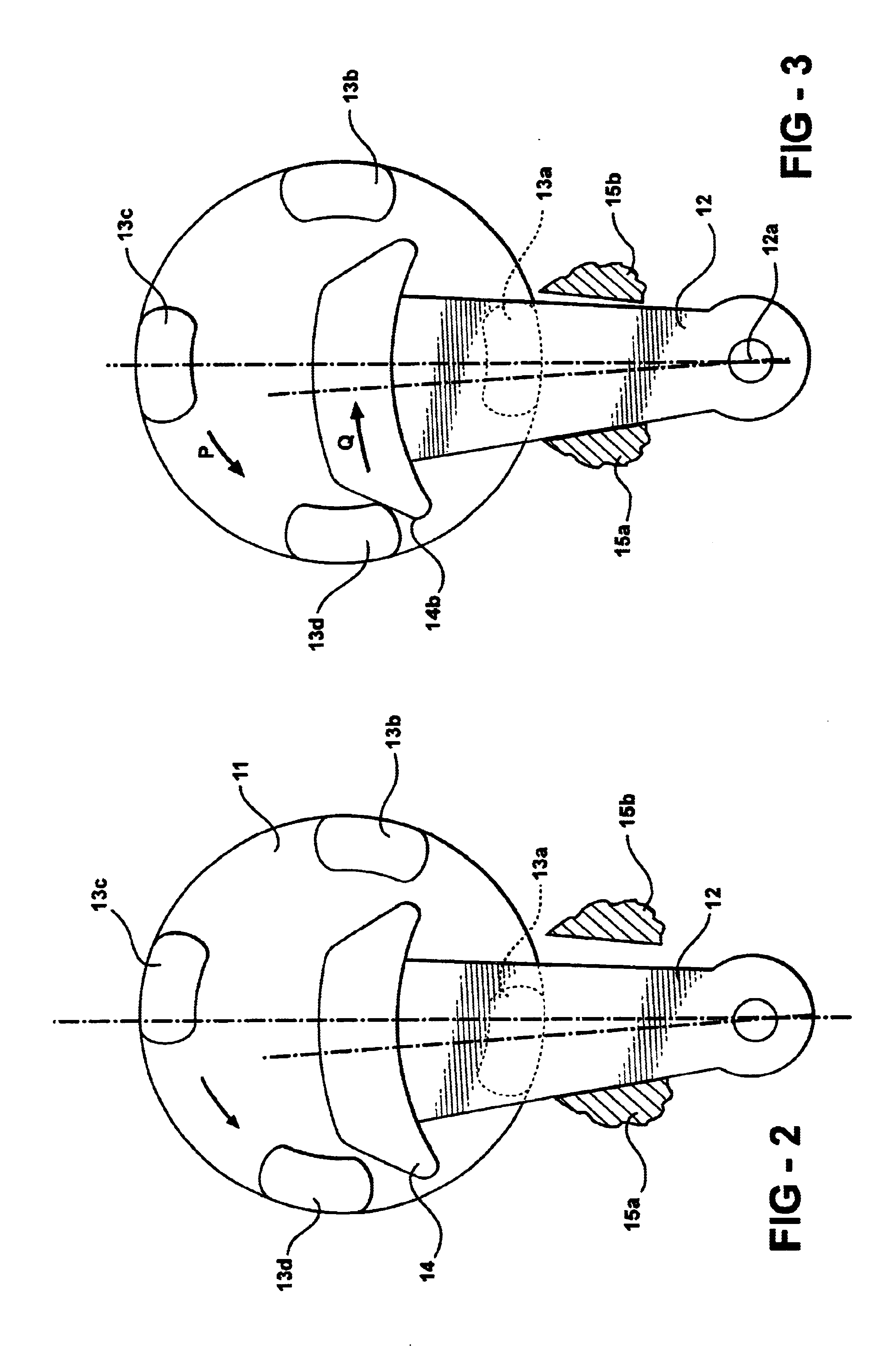
[0029]The device 10 comprises a cam or worm wheel 11 constructed with at least one cam 13 extending out from the cam wheel 11. In the preferred embodiment, at least one cam 13 includes a plurality of cams 13a to 13d, each of the plurality of calms 13a to 13d spaced around the circumference of cam wheel 11. Cam wheel 11 is driven by an electric motor 21. The electric motor 21 is reversible so that the cam wheel 11 can be rotated in both directions of ration about a real or virtual rotation axis 11a.

[0030]The device 10 further comprises an adjustment lever 12 which is pivotable about a (real or virtual) axis 12a.

[0031]The pivoting action of the adjustment lever 12 is limited by two stops 15a, 15b which simultaneously define end positions of the adjustment lever. The end position of the adjustment lever 12 in which the lever abuts on the stop 15a corresponds, for example, to a ...


PUM


Abstract

An actuating device, particularly for a vehicle door lock, having a cam wheel (11) comprising at least one cam (13), the cam wheel being selectively rotatable about a rotation axis (11a) in two directions, and an adjustment lever (12) comprising a dog (14), the lever (12) being pivotable about a rotation axis (12a) by interaction between the at least one cam (13) and the dog (14), between two stop or end positions. The dog (14) has a first actuation curve (14a) and at least one second actuation curve (14b). Interaction between the at least one cam (13) and the first actuation curve (14a) on the dog (14) causes no pivoting of the adjustment lever (12), and interaction of the at least one cam (13) with the at least one second actuation curve (14b) on the dog (14) initiates pivoting of the adjustment lever (12) between the two stops.

Description

BACKGROUND OF THE INVENTION[0001]1. Field of Invention[0002]The present invention relates to an actuating device or an actuator, particularly for a vehicle door lock.[0003]2. Description of the Related Art[0004]It may be expedient, for example, in central locking systems in motor vehicles, to provide a manual opening option in addition to automatic opening or servo opening. This mechanical back-up can ensure that the central locking system or the individual locks can still be operated even if the vehicle's on-board electronics fail.[0005]However, the provision of a mechanical back-up incurs greater costs and adds weight.[0006]DE 199 13 590 A1 describes a central locking system for a motor vehicle wherein a central locking lever can be moved by an electric motor or automatically, by means of a power take-off pulley formed with eccentric pins. In addition to this automatic movement, manual movement is also possible, the disadvantage being that mechanically and / or electrically produced...

Claims


Application Information

Patent Timeline
Patent Type & Authority Patents(United States)
IPC IPC(8): E05B65/12E05B17/00
CPCE05B81/25E05B77/38E05B81/90Y10T292/1082Y10T292/1047
Inventor SHAFRY, GAVRIEL
Owner INTIER AUTOMATIVE CLOSURES INC
Learn More