Stirling engine

Inactive Publication Date: 2005-04-05
SHARP KK
View PDF5 Cites 11 Cited by
  • Summary
  • Abstract
  • Description
  • Claims
  • Application Information

AI Technical Summary

Benefits of technology

An object of the present invention is to provide a Stirling-cycle engine in which the center position of the reciprocating movement of its piston is stabilized by forming grooves in the piston easily and cheaply. Another object of the present invention is to provide a Stirling-cycle engine with a reduced gas flow loss from the working space. Still another object of the present invention is to provide a Stirling-cycle engine in which the flow of the working medium does not spoil the smooth sliding of the piston achieved by an air bearing.
To achieve the above objects, according to the present invention, a Stirling-cycle engine is provided with a piston that reciprocates inside a cylinder and a displacer that reciprocates inside the cylinder as a result of a working medium being compressed or expanded by the reciprocating movement of the piston, and the piston and the displacer are arranged so that their center axes coincide with the center axis of the cylinder. Moreover, the stirling-cycle engine has a first space formed between the displacer and the piston, a second space formed so as to extend from the side of the piston facing away from the displacer and include a portion adjacent to at least part of the side wall of the cylinder, a third space formed on the side of the displacer facing away from the piston, a first groove formed so as to run from the end surface of the piston facing the first space in the direction of the reciprocating movement, and a second groove formed around the periphery of the piston so as to cross the first groove, and a hole formed through the side wall of the cylinder. This Stirling-cycle engine is so structured that, when the piston is in the center position of its reciprocating movement, the second groove and the hole connect to each other so that the first and second spaces communicate with each other. Here, the opening of the hole has the shape of an elongate circle or a rectangle having its minor axis or shorter sides aligned with the direction of the reciprocating movement of the piston. This helps shorten the time for which the second groove and the hole connect to each other during the reciprocating movement of the piston.
Here, the second groove may be so formed that its depth is greater than its width as viewed in a cross section. This helps reduce the time for which the second groove and the hole connect to each other during the reciprocating movement of the piston.
Alternatively, the first groove may be so formed that its depth is greater than its width as viewed in a cross section. This helps reduce the proportion of the area occupied by the first groove relative to the surface area of the slide surface of the piston.
Alternatively, the first groove may be given increasingly large cross-sectional areas from one end thereof toward the other end thereof so that the first groove has the maximum cross-sectional area at the other end thereof facing the first space. This helps reduce the energy loss due to the flow of working medium.

Problems solved by technology

However, owing to various factors, such as the influence of thermal expansion and the wear of the seal ring after a prolonged period of operation, perfect sealing is impossible here, and thus a very small gap appears between the cylinder slide surface 3a and the piston slide surface 1b. When the engine is driven, the piston 1 reciprocates and produces changes in the pressure of the working medium in the first space 7a and the second space 8.
As a result, as the pressure of the working medium in the first space 7a lowers, problems arise, such as lower cooling performance than expected, or collision between the piston 1 and the displacer 2 resulting from the center position of the reciprocating movement of the piston 1 being displaced from the initially set position.
This, however, is not at all effective against the leakage of the working medium out of the first space 7a, and only invites an increase in the power required by the driving means for driving the piston 1, leading to an increase in the input electric power.
This leads to another problem, lower cooling efficiency.
Moreover, a gas flow loss occurs in the first and second grooves 10a and 10b. This increases the input of power required to operate the piston 1, and thus makes it impossible to enhance the performance of the Stirling-cycle engine as expected.

Method used


Image

  • Stirling engine
  • Stirling engine
  • Stirling engine

Examples


first embodiment

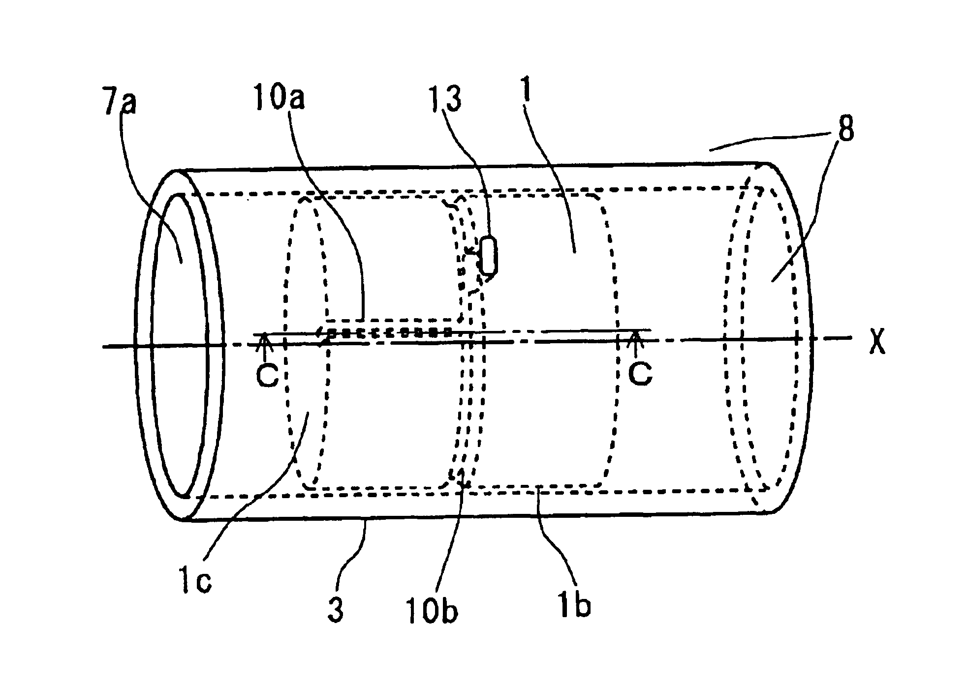
FIG. 1A is a perspective view of the piston and the cylinder of the invention. Initially, the piston 1 is in the center position of its reciprocating movement where it is designed that equilibrium of pressure is achieved between the first space 7a and the second space 8. In the piston slide surface 1b, a first groove 10a is formed so as to run from the piston end surface 1c facing the first space 7a in the direction X of the reciprocating movement, and a second groove 10b is formed all around the periphery of the piston 1 so as to cross the first groove 10a. Moreover, in the cylinder 3, a hole 13 is formed so as to penetrate from the second groove 10b to the second space 8. Thus, during the reciprocating movement of the piston 1, only the moment that the second groove 10b and the hole 13 communicate with each other, the first space 7a and the second space 8 communicate with each other so that equilibrium of pressure is achieved between the first space 7a and the second space 8. Sinc...

second embodiment

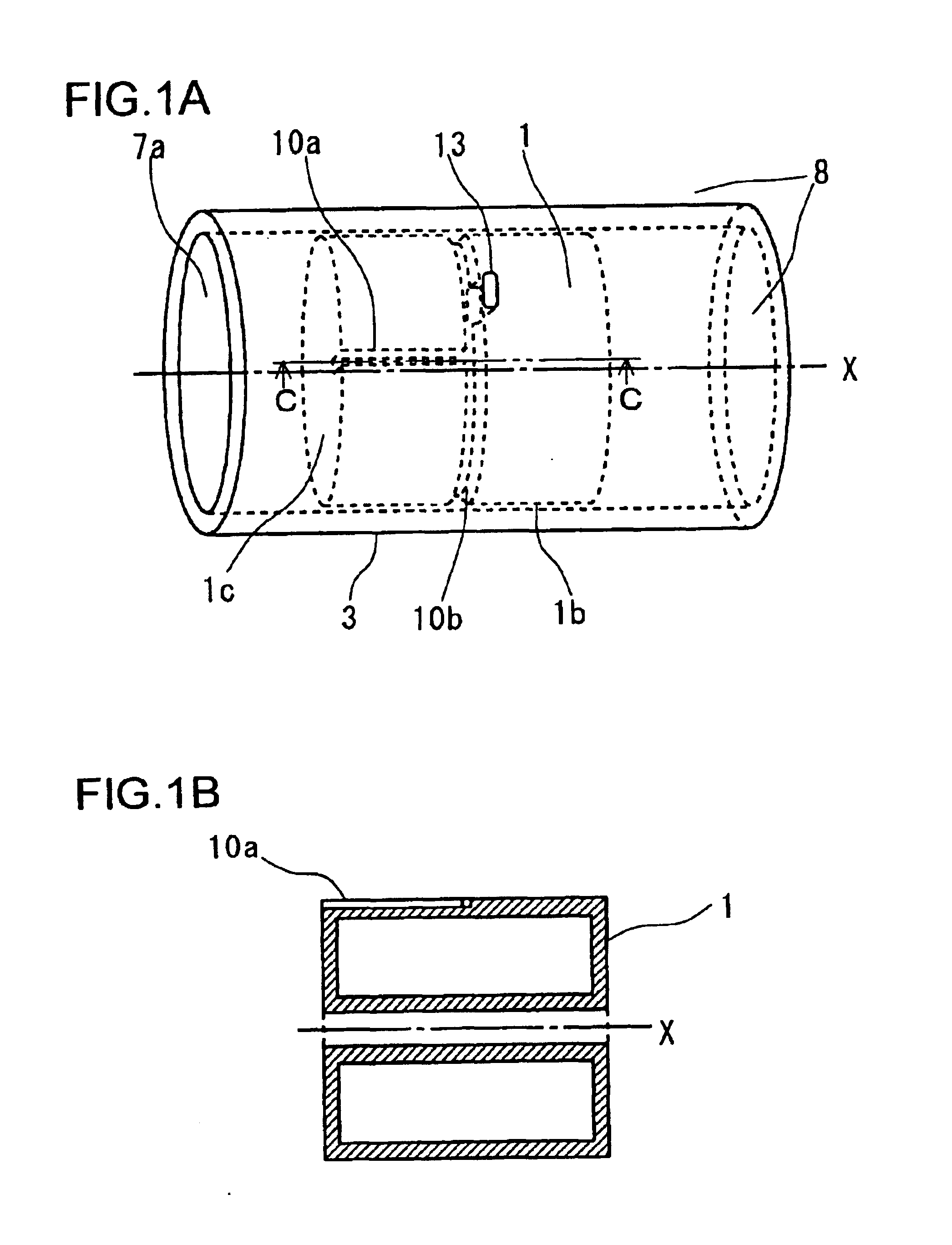
FIG. 2 is a perspective view of the piston and the cylinder of the invention. The piston 1 is in the center position of its reciprocating movement as initially set. In the piston slide surface 1b, a first groove 10a is formed so as to run from the piston end surface 1c facing the first space 7a in the direction X of the reciprocating movement, and a second groove 10b is formed all around the periphery of the piston 1 so as to cross the first groove 10a. Moreover, in the cylinder 3, a plurality of (in FIG. 2, two) holes 14 are formed so as to penetrate from the second groove 10b to the second space 8. Since the second groove 10b is formed all around the periphery of the piston 1, even if the piston 1 rotates about its axis while moving, the second groove 10b can communicate with the hole 14.

Here, where a plurality of holes 14 are formed, by making the total of the diametrical cross-sectional areas of the holes 14 equal to the cross-sectional area of the single hole 14 in a case where...

third embodiment

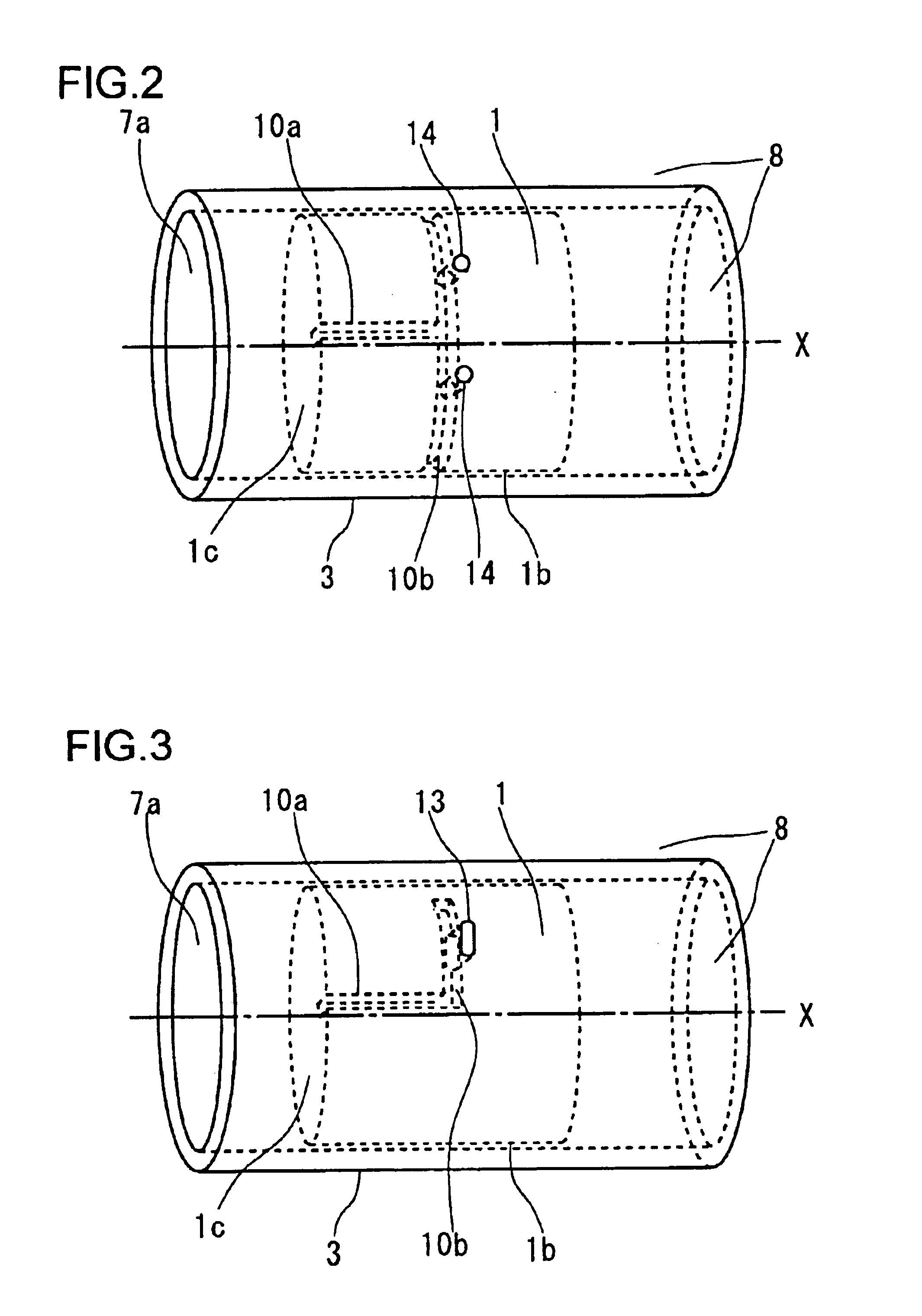
FIG. 3 is a perspective view of the piston and the cylinder of the invention. The piston 1 is in the center position of its reciprocating movement as set initially, and is provided with a means (for example the piston support spring 5 shown in FIG. 10) for restricting the rotation of the piston 1 about its axis. In the piston slide surface 1b, a first groove 10a is formed so as to run from the piston end surface 1c facing the first space 7a in the direction X of the reciprocating movement, and a second groove 10b is formed in the periphery of the piston 1 so as to extend from one point on the first groove perpendicularly to the first groove (in FIG. 3, L-shaped). The second groove 10b is formed only where the hole 13 and the second groove 10b communicate with each other through the shortest path, and the opening of the hole 13 is formed in the shape of an elongate circle. The opening of the hole 13 may formed in any other shape as long as it helps shorten the time for which the seco...


PUM


Abstract

A free-piston type Stirling engine used for producing cold heat with the vibration center position of a piston accurately kept. A first space is formed on one side of a piston, and a second space is formed on the opposite side to spread up to a portion adjacent to a cylinder's side wall. A piston is provided with a vibration-direction first groove extending up to the first space and a circumferential-direction second groove, and a cylinder is provided with a hole penetrating the side wall thereof. The second groove of the piston, when coupled with the cylinder's hole during a piston vibration process, allows the first space to communicate with the second space. Accordingly, a short-time communication between the first and second spaces will balance pressures in the two spaces against each other to keep the vibration center position of the piston accurately.

Description

TECHNICAL FIELDThe present invention relates to a Stirling-cycle engine used to produce cold (cryogenic heat), and more particularly to a Stirling-cycle engine that can precisely maintain the center position of the reciprocating movement of the piston thereof.BACKGROUND ARTA free-piston-type Stirling-cycle engine designed for the production of cold is also called a reversed-Stirling-cycle engine in terms of the thermodynamic cycle on which it is based. FIG. 10 shows a sectional view of a conventional Stirling-cycle engine. A typical Stirling-cycle engine has a piston 1 and a displacer 2 that reciprocate linearly inside a cylinder 3. The piston 1 and the displacer 2 are arranged coaxially, and a rod 2a formed on the displacer 2 penetrates the piston 1 through a slide hole 1a formed at its center. Thus, the piston 1 and the displacer 2 are smoothly slidable along the cylinder inner slide surface 3a. Moreover, the piston 1 and the displacer 2 are resiliently supported on a pressure ves...

Claims


Application Information

Patent Timeline
IPC IPC(8): F02G1/00F02G1/053F02G1/043F25B9/14
CPCF02G1/0435F25B9/14F02G1/0535F02G1/053
Inventor OGURA, YOSHIAKI
Owner SHARP KK
Why Eureka
Try Eureka