Lintel form for concrete and block constructions

Inactive Publication Date: 2011-12-13
HOY JOHN
View PDF26 Cites 9 Cited by
  • Summary
  • Abstract
  • Description
  • Claims
  • Application Information

AI Technical Summary

Problems solved by technology

The references of the background art fail to overcome the significant limitations and d

Method used


Image

  • Lintel form for concrete and block constructions
  • Lintel form for concrete and block constructions
  • Lintel form for concrete and block constructions

Examples


Embodiment Construction

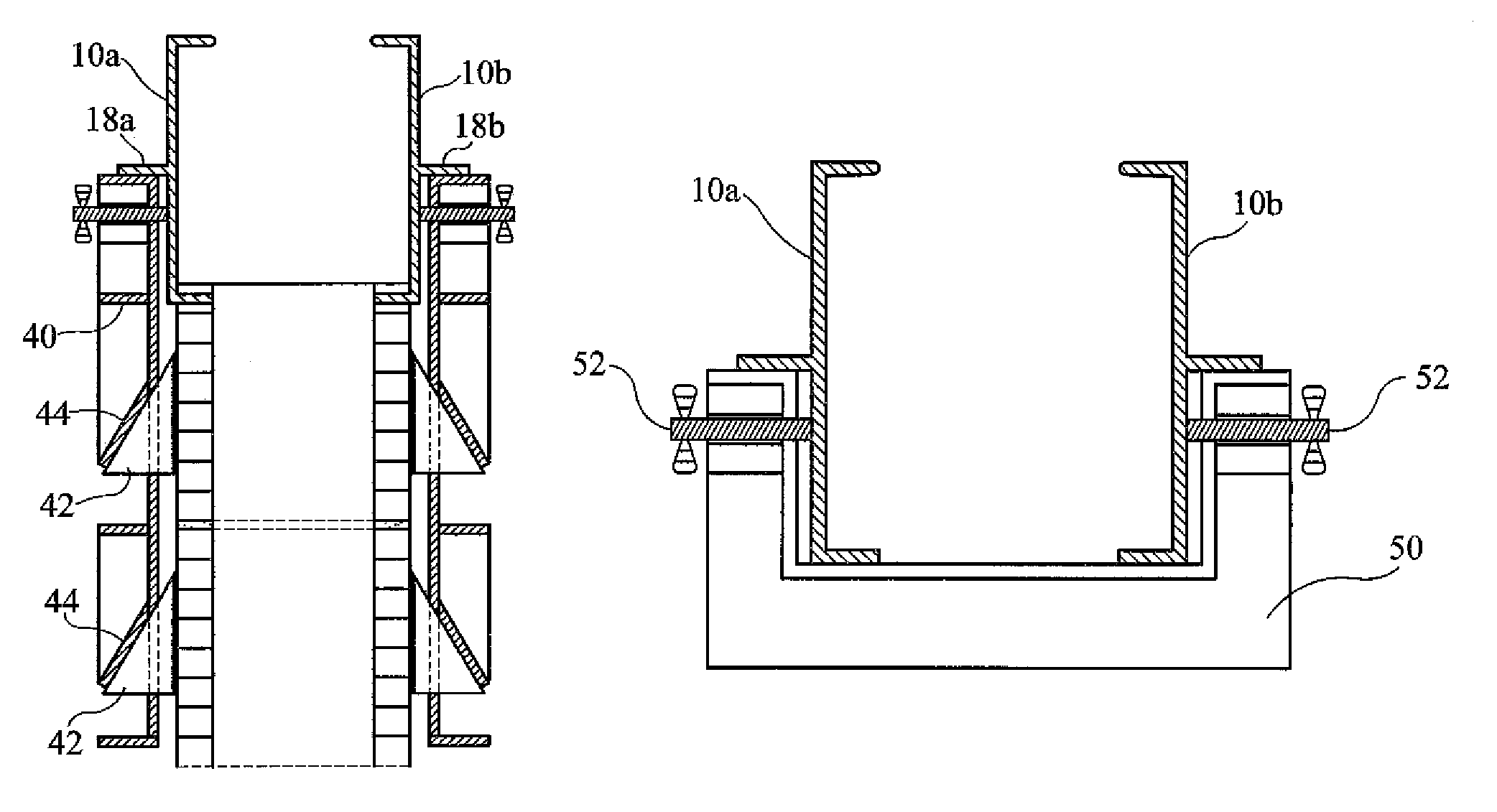
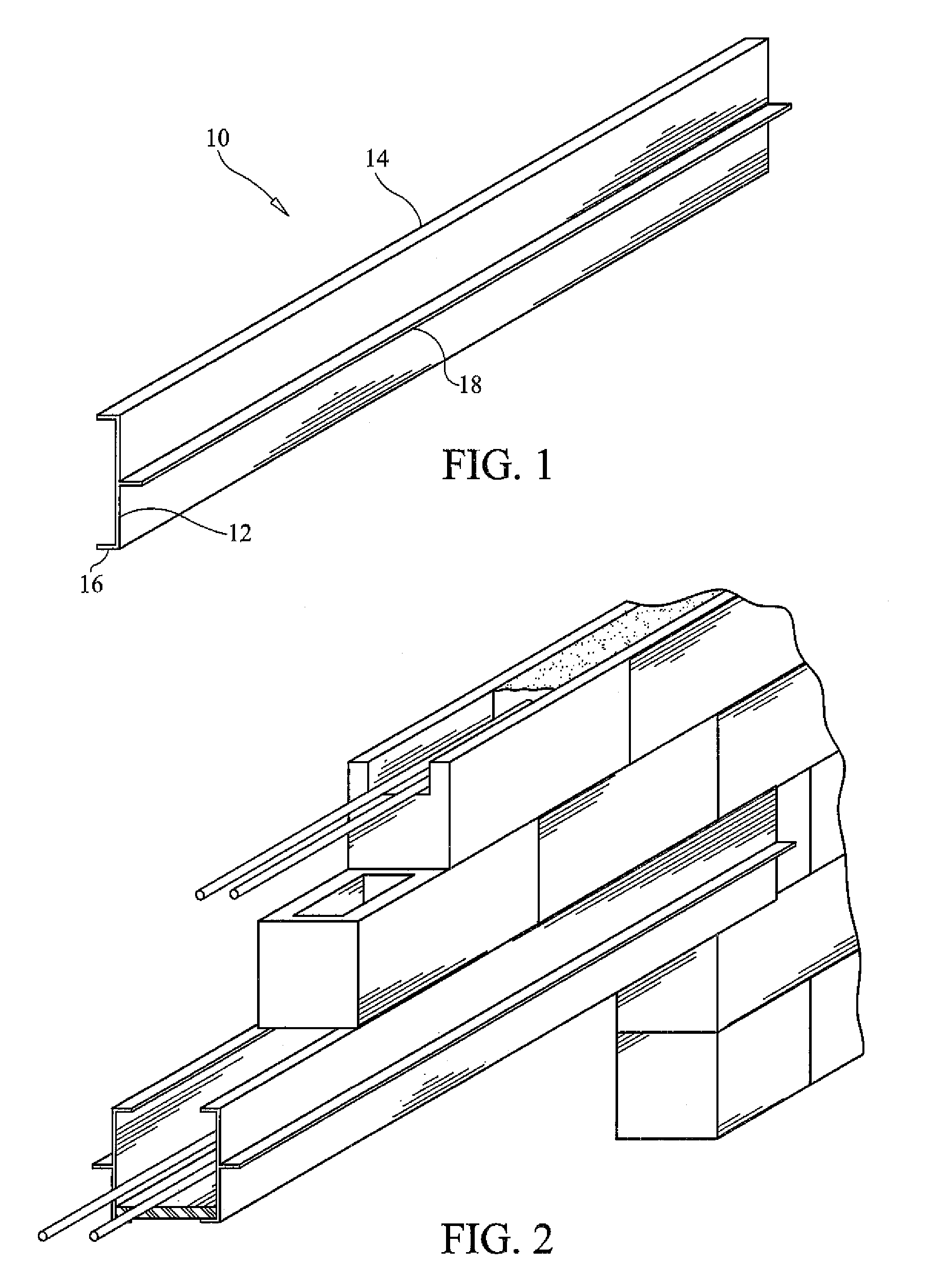
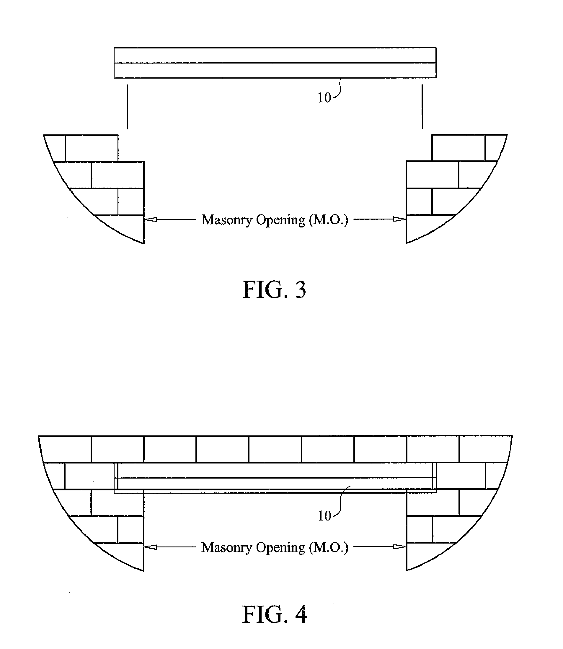
[0046]With reference to the drawings, FIGS. 1-17 depict and illustrate an improved concrete lintel form, generally referenced as 10, in accordance with the present invention. As best seen in FIG. 1, lintel form 10 comprises a generally an elongate form member. Lintel form 10 is typically used as part of a pair of form members installed in opposing face-to-face relation spanning a structure opening, such as a window or door opening to form a lintel form cavity as illustrated in FIG. 2. Each form member 10 includes a generally vertical side wall 12 having inwardly projecting top and bottom support legs, referenced 14 and 16 respectively, running the substantially the entire length of the member. When a pair of form members 10 are disposed in face-to-face relation, the top legs 14 function to support masonry block stacked on top of the form to allow for the construction of a composite cast in place beam. The bottom legs 16 function to support a bottom form that may be inserted after ma...


PUM


Abstract

A concrete lintel form includes a pair of elongate side members for installation in opposing face-to-face relation spanning a structure opening, such as a window or door opening, for fabrication of concrete beams or composite concrete masonry beams. Each form member comprises a generally vertical sidewall having inwardly projecting top and bottom legs running the substantially the entire length of the member. The top legs function to support masonry block stacked on top of the form to allow for the construction of a composite cast in place beam. The bottom legs function to support a bottom form that may be inserted after masonry has been stacked and secured with mortar, thereby allowing the workers to leave an opening that allows mortar droppings to fall through and not collect in the form. Each form member includes at least one outwardly projecting stiffener running substantially the entire length of the member between the top and bottom. The stiffener functions to resist outward expansion of the form as concrete is placed therein thereby minimizing bracing requirements.

Description

CROSS REFERENCE TO RELATED APPLICATIONS[0001]This application claims the benefit of provisional U.S. Patent Application Ser. No. 60 / 902,802, filed on Feb. 22, 2007.STATEMENT REGARDING FEDERALLY SPONSORED RESEARCH OR DEVELOPMENT[0002]N / ACOPYRIGHT NOTICE[0003]A portion of the disclosure of this patent document contains material that is subject to copyright protection. The copyright owner has no objection to the facsimile reproduction by anyone of the patent document or patent disclosure as it appears in the Patent and Trademark Office patent file or records, but otherwise reserves all copyrights rights whatsoever.BACKGROUND OF THE INVENTION[0004]1. Field of the Invention[0005]The present invention relates to construction of beams over concrete masonry openings, and more particularly, to apparatus and methods for forming and constructing beams over openings in concrete or block constructions.[0006]2. Description of Related Art[0007]A lintel or header is a horizontal beam used in the co...

Claims


Application Information

Patent Timeline
IPC IPC(8): E04G13/04
CPCE04G13/04E04C3/02E04C2003/023
Inventor HOY, JOHN
Owner HOY JOHN
Why Eureka
Try Eureka