Foot actuated switch

a switch and foot technology, applied in the field of switches, can solve the problems of restricted working under microscope magnification, dentist's hands are unavailable to activate dental instruments or otherwise operate the same, and dentist's hands may not have the freedom to adjust the focus and/or zoom of microscopes, so as to minimize muscular activities and movement during activation, prevent interruption of procedures, and minimize body movement. the effect of activation

Active Publication Date: 2011-12-13
MORA ASSAD F
View PDF19 Cites 3 Cited by
  • Summary
  • Abstract
  • Description
  • Claims
  • Application Information

AI Technical Summary

Benefits of technology

[0011]The present invention provides a foot control unit having a plurality of switches for use by a dentist, surgeon, or other professional that is ergonomically designed to minimize body movement during activation and to prevent interruptions of the procedure being performed that may be caused by the same. In one exemplary embodiment, the design provides for the operator's, e.g., the dentist's, foot to be continuously and comfortably supported in a neutral muscular-skeletal position by a portion of the foot control unit both at rest and during activation. By providing the foot with a neutral muscular-skeletal position at rest, the position of each of the switches may be kept at a substantially minimal and substantially equal distance from a corresponding activating part of the foot. This allows for the foot control unit of the present invention to minimize muscular activities and movement during activation.
[0012]In one exemplary embodiment, the foot control unit of the present invention includes a base plate, a rear heel support extending upwardly from a base plate, and a pair of switches positioned on the base plate. The rear heel support provides an area upon which the heel of the dentist's foot may rest during a dental procedure. In one exemplary embodiment, the heel support is elevated relative to switches mounted on the base plate, which allows the dentist's foot to hang from the heel support with the toes positioned below the heel, i.e., below the top surface of the heel support upon which the heel of the dentist is supported. Additionally, the heel support may also facilitate positioning the dentist's foot with a lateral side of the dentist's foot positioned closer to the base plate and the medial side of the dentist's foot positioned further from the base plate. Stated another way, the lateral side of the dentist's foot is positioned closer to the ground on which the base plate is supported and the medial side of the patient's foot is positioned further from the ground on which the base plate is supported.
[0013]With the dentist's foot supported on the heel support of the foot control unit of the present invention in the manner described above, a first, acute angle is formed between the floor on which the base plate is supported and the longitudinal axis of the sole of the dentist's foot. Additionally, as a result of the lateral side of the dentist's foot being lower that its medial counterpart, a second angle is formed with the floor on which the base plate is supported and the sole of the dentist's foot in a direction perpendicular to the longitudinal axis of the dentist's foot. By allowing the dentist's foot to rest on the heel support in the position described above, the dentist's foot is maintained in a neutral muscular-skeletal position, which eliminates the stress and fatigue that may be experienced when using prior art foot switches. Further, as a result of the dentist's heel being positioned on the heel support, a substantial downward pressure is exerted on the base plate by the weight of the dentist's leg. As a result, the base plate and, correspondingly, the switches mounted thereon remain in the desired position. Further, having the foot resting comfortably on the heel while the toes are in a position in which slight movement will allow them to activate the switches on the base plate eliminates the need for the dentist to make visual contact with the foot control unit in order to realign the foot with a switch of the foot control unit and also eliminates any associated peripheral body movement.
[0014]In one exemplary embodiment, a pair of switches is positioned on the base plate. Each of the pair of switches may be inclined relative to the base plate. For example, the lateral side of each of the pair of switches may be elevated relative to both the base plate and the corresponding medial side of each switch. By elevating the lateral sides of the switches relative to both the medial sides of the switches and the base plate upon which the switches are positioned, the switches may be placed substantially adjacent one another and the dentist's foot may be utilized to actuate either of the switches without substantially simultaneously depressing both switches. Thus, the dentist may depress a corner of the medial side of either of the switches without unintentionally depressing a portion of the adjacent switch. This allows for each of the switches to be depressed with substantially minimum muscular-skeletal activity in the foot and leg and, correspondingly, substantially minimum subsequent body movement during a dental procedure.
[0015]Alternatively, in another exemplary embodiment, the medial side of each of the pair of switches is elevated relative to both the base plate and the corresponding lateral side of each of the pair of switches. This provides a substantially similar benefit as described above with respect to elevating the lateral side of each of the pair of switches. In another exemplary embodiment, one of the pair of switches is located further forward, i.e., further anterior in relation to the user's body, relative to the position of the other switch to better correspond to the position and the actuation movement of the foot.

Problems solved by technology

As a result, the dentist's hands are unavailable to activate the dental instruments or otherwise operate the same.
For example, if a dental procedure requires the use of a dental microscope, the dentist may lack a free hand to adjust the focus and / or zoom of the microscope.
For example, foot switches may be used in conjunction with a microscope to control the zoom of the microscope, as working under microscope magnification is restrictive in many ways.
Otherwise, the operator would have to work in a field that is not in sharp focus until the operator can no longer readily differentiate objects in the operating field.
While known foot switches are effective, several drawbacks remain.
However, making visual contact may be difficult, as the inclined plate is often positioned beneath the patient's head and / or body when the patient is in a reclined position during a dental procedure.
This results in the dentist having to remove the dental instrument from the patient's oral cavity and stop the progress of the dental procedure in order for the dentist to make visual contact with the inclined plate and to realign the dentist's foot with the switch.
Additionally, since there is nothing that facilitates the retention of the inclined plate and base in position, the inclined plate and base may move as a result of a switch being depressed.
However, for the same reasons identified above, this causes the dentist to pause or otherwise stop the dental procedure.
Further, if the dentist attempts to keep their foot in position and lifted from the inclined plate of the switch, the dentist is forced to hold their foot in an unnatural position in which the ball and toes of the foot are elevated relative to the heel of the foot.
However, maintaining the foot in this type of position may result in substantial stress and fatigue on the dentist's ankle and / or foot.
Any uncontrolled movements of the body and / or the hands of a dentist during a dental procedure, particularly when being viewed under microscope magnification, may cause an unwanted interruption of the dental procedure.
Further, as a result of the dentist's heel being positioned on the heel support, a substantial downward pressure is exerted on the base plate by the weight of the dentist's leg.

Method used


Image

  • Foot actuated switch
  • Foot actuated switch
  • Foot actuated switch

Examples


Embodiment Construction

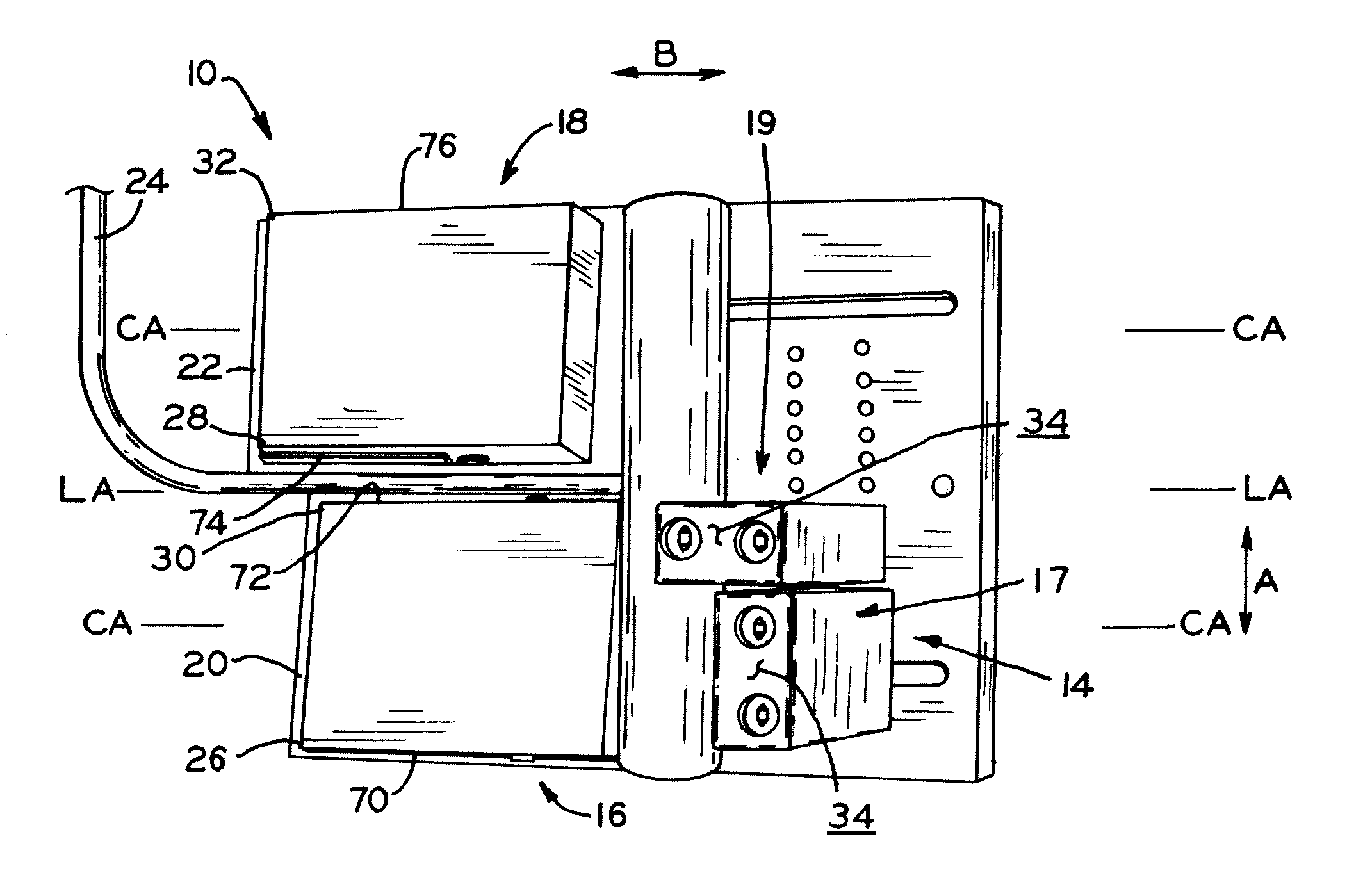
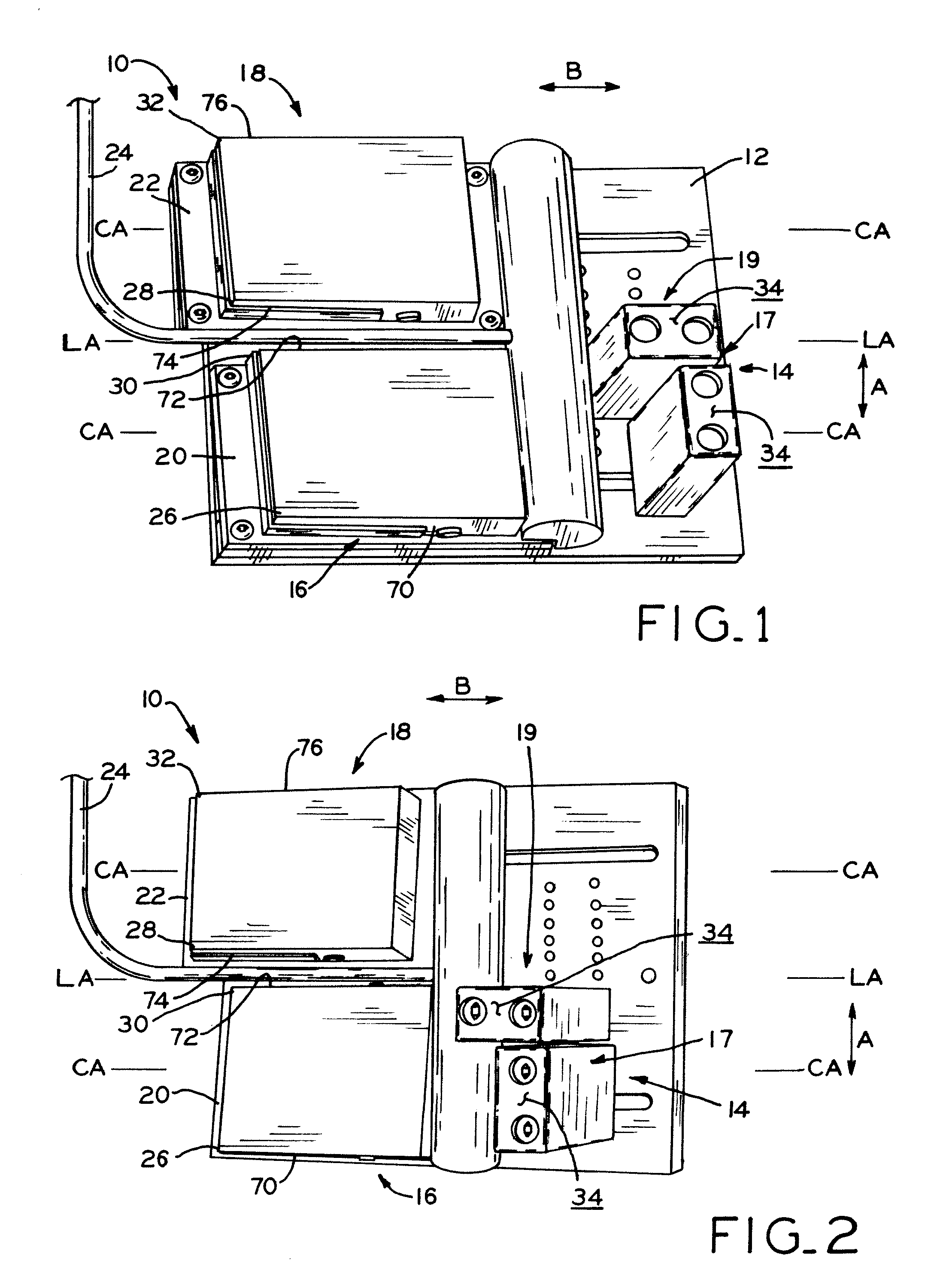
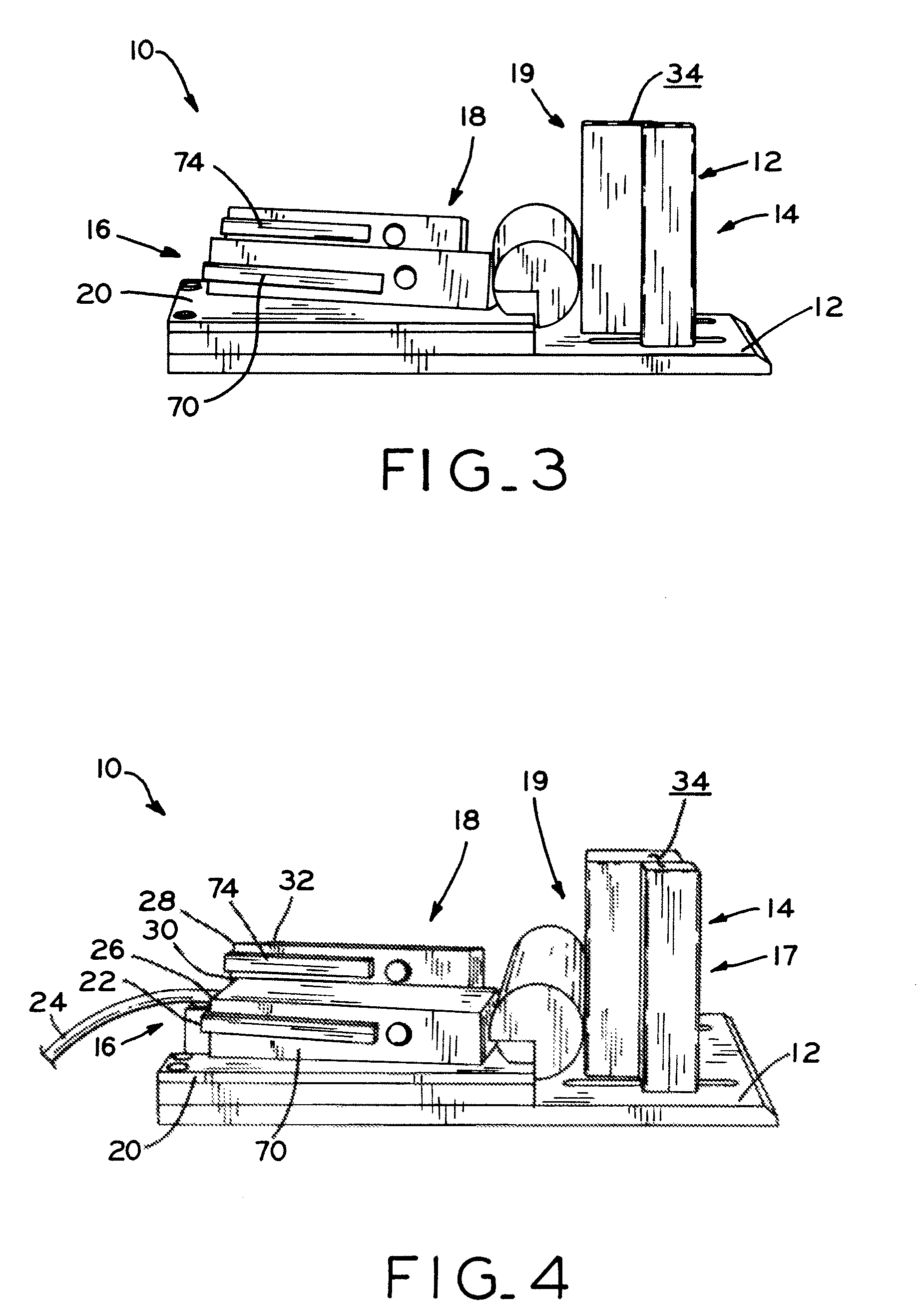
[0031]Referring to FIG. 1, foot control unit 10 of the present invention is shown. Foot control unit 10 includes base plate 12 having heel support 14 secured thereto and switches 16, 18 positioned thereon. Heel support 14 extends upward from base plate 12 and is designed to support the heel of a dentist's foot during a dental procedure, as described in detail below. While described in detail herein with specific reference to use by a dentist during a dental procedure, foot control unit 10 may be used by any individual and in any situation in which the foot operated control of instruments and / or machinery is desirable, such as by a surgeon or a musician. Additionally, while described and depicted herein with specific reference to two switches, i.e., switches 16, 18, the present invention may be utilized in conjunction with any number of switches. In one exemplary embodiment, switches 16, 18, are “Treadlight” switches commercially available from LINEMASTER Switch Corporation, 29 Plain...


PUM


Abstract

The present invention provides a foot control unit having a plurality of switches for use by a dentist, surgeon, or other professional that is ergonomically designed to minimize body movement during activation and to prevent interruptions of the procedure being performed that may be caused by the same. In one exemplary embodiment, the design provides for the operator's, e.g., the dentist's, foot to be continuously and comfortably supported in a neutral muscular-skeletal position by a portion of the foot control unit both at rest and during activation. By providing the foot with a neutral muscular-skeletal position at rest, the position of each of the switches may be kept at a substantially minimal and substantially equal distance from a corresponding activating part of the foot. This allows for the foot control unit of the present invention to minimize muscular activities and movement during activation.

Description

CROSS-REFERENCE TO RELATED APPLICATIONS[0001]This application claims the benefit under Title 35 U.S.C. §119(e) of U.S. Provisional Patent Application Ser. No. 61 / 095,858, entitled FOOT ACTIVATED SWITCH, filed on Sep. 10, 2008, the entire disclosure of which is expressly incorporated by reference herein.BACKGROUND[0002]1. Field of the Invention[0003]The present invention relates to switches, and, particularly, to foot actuated switches.[0004]2. Description of the Related Art[0005]During a dental procedure, a dentist's hands are positioned in or around a patient's oral cavity. For example, the dentist's hands may grasp a dental mirror, dental drill, suction tube, or other dental instrument in order to use the same during the procedure. As a result, the dentist's hands are unavailable to activate the dental instruments or otherwise operate the same. For example, if a dental procedure requires the use of a dental microscope, the dentist may lack a free hand to adjust the focus and / or zo...

Claims


Application Information

Patent Timeline
Patent Type & Authority Patents(United States)
IPC IPC(8): H01H3/14
CPCA61G13/02A61G15/02
Inventor MORA, ASSAD F.
Owner MORA ASSAD F
Why Eureka
Try Eureka