Micromechanical component and method for producing a micromechanical component

a micro-mechanical and component technology, applied in the direction of fluid pressure measurement, fluid pressure measurement by electric/magnetic elements, instruments, etc., can solve the problems of gas diffuse into the gel, low stability, and damage to bonding wires running in the gel, so as to reduce stress coupling, high stability or load carrying capacity, and low strength

Active Publication Date: 2011-12-13
ROBERT BOSCH GMBH
View PDF9 Cites 11 Cited by
  • Summary
  • Abstract
  • Description
  • Claims
  • Application Information

AI Technical Summary

Benefits of technology

[0005]By contrast, the micromechanical component according to the present invention has the advantage that the substrate in the contact region acquires a higher stability or load carrying capacity. Such a backside contacting also reduces stress coupling on the front side of the micromechanical component, for instance, in case of a flip-chip mounting. The diaphragm, within the meaning of the present invention, is made up of the substrate material, that is usually silicon. The term “mechanically stable diaphragm”, within the meaning of the present invention, denotes a diaphragm which makes a contribution to the load carrying capacity of the substrate. Thus, the diaphragm is able to have a low strength compared to the substrate. Within the meaning of stability, a diaphragm is advantageous which has a strength that amounts to one-half of the strength of the substrate, for example. Within the meaning of the present invention, the term contact region designates the entire region between the front side and the backside of the substrate in which the contact holes are provided. A higher stability in the contact region advantageously permits larger contact holes, that is, contact holes having a larger cross section. This creates the advantageous possibility of etching the contact holes using a higher etching rate, which simplifies and speeds up the production process for the micromechanical component according to the present invention. The functional pattern has, for instance, etched and / or doped areas which make possible the actual chip function of the micromechanical component according to the present invention, such as a sensor patterning. The design of the micromechanical component according to the present invention is simple and cost-effective to produce, and is particularly suitable for micromechanical sensors, especially pressure sensors. Particularly advantageously the micromechanical component according to the present invention is able to be used as a pressure sensor in high pressure ranges, for instance, at 10 bar and higher. Because of the design according to the present invention, the micromechanical component is also particularly suitable for absolute or for differential pressure measurement in chemically aggressive environments, such as in the field of particle filters. Additional fields of application, in which, for instance, the use of a component having a passivating gel is not possible, or is at least difficult, may be covered by the micromechanical component according to the present invention, for example, as sensor for the tire pressures of vehicle, or as a pressure sensor for air bags, especially side air bags.
[0007]According to one specific example embodiment it is provided that the front side of the substrate has an epitaxial layer, the contact hole extending up to the epitaxial layer or into the epitaxial layer. An oxide layer is particularly preferably situated between the substrate and the epitaxial layer, at least in the contact region, which advantageously may be used as a stop oxide layer for a trench etching process, which greatly improves the tolerance in the production of the contact holes.
[0009]One further subject matter of the present invention is a method for producing a micromechanical component, at least one contact hole being applied into the substrate from the direction of the backside in such a way that the mechanically stable diaphragm remains between the contact hole and the front side, the electrical contact between the functional pattern and the backside being produced all the way through the diaphragm. Using the method according to the present invention, advantageously substrates having high stability in the contact region may be produced, which, for instance, permits larger contact holes, and thus the etching having a higher etching rate. The production according to the present invention is therefore advantageously particularly simple and rapid.

Problems solved by technology

Passivating using gel has the disadvantage that gas diffuses into the gel, especially if it is under high pressure.
When the dissolved gas becomes gaseous again, for instance in response to a pressure drop, the bonding wires running in the gel, which make contact with the chip, may be destroyed.
An electrical plated-through hole to the backside of the substrate is also known, from published German patent document DE 103 59 217 A1, such a design being comparatively thin in the area of the contact holes, and thus not very stable.

Method used


Image

  • Micromechanical component and method for producing a micromechanical component
  • Micromechanical component and method for producing a micromechanical component
  • Micromechanical component and method for producing a micromechanical component

Examples


Embodiment Construction

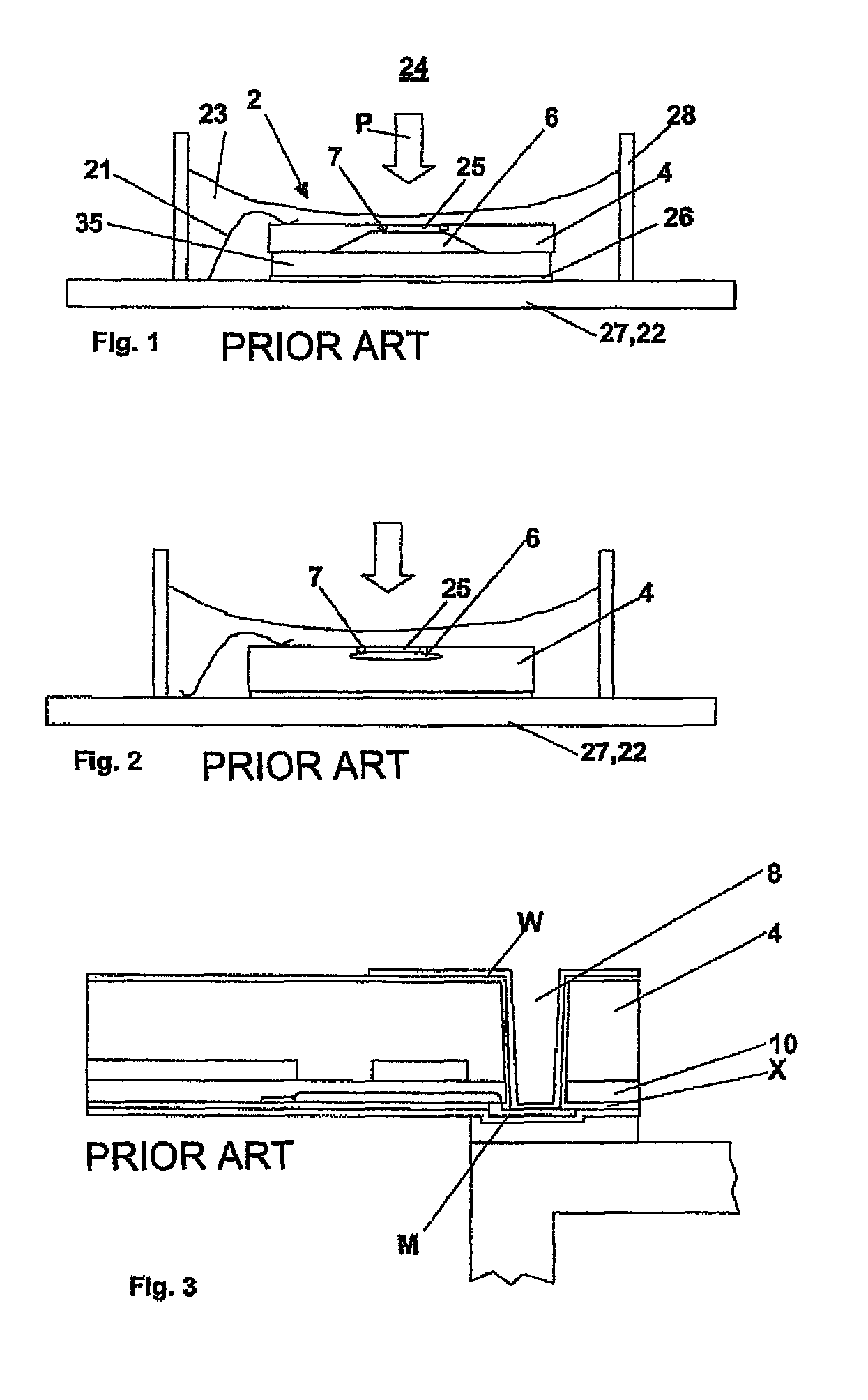
[0020]FIG. 1 shows the design of a micromechanical silicon pressure sensor having a functional pattern 7, in this case using piezoresistive converter elements. A substrate 4 has a front side 2, which faces a pressure medium 24. The pressure of the medium 24 acts on the pressure sensor in the direction of arrow P. On front side 2 of substrate 4 there is a sensor diaphragm 25 having functional patterns 7, in this case using piezoresistive converter elements. Behind sensor diaphragm 25, a recess 6 is etched anisotropically into substrate 4. Because of anodic bonding of substrate 4 onto a pyrex glass 35, recess 6 forms a cavity 6 between substrate 4 and pyrex glass 35. The composite of substrate 4 and pyrex glass 35 is connected to a printed-circuit board 22 or a housing 27, a premold housing, for instance, by an adhesive layer 26 or a solder layer 26. Front side 2 of substrate 4 is connected electrically conductively to printed-circuit board 22, using a bonding wire 21. A gel ring 28 o...


PUM


Abstract

A micromechanical component includes a substrate that has a front side and a backside, the front side having a functional pattern, which functional pattern is electrically contacted to the backside in a contact region. The substrate has at least one contact hole in the contact region, which extends into the substrate, starting from the backside.

Description

BACKGROUND OF THE INVENTION[0001]1. Field of the Invention[0002]The present invention relates to a micromechanical component, e.g., a pressure sensor.[0003]2. Description of Related Art[0004]A micromechanical device, in particular a pressure sensor, is known from published German patent document DE 103 23 559 A1, the pressure sensor being based on a piezoresistive converter principle for converting a mechanical force into an electrical signal. One usual construction of a micromechanical pressure sensor having piezoresistive converter elements is shown in FIG. 1. A substrate having an anodically etched diaphragm is bonded anodically onto glass. It is also known according to published German patent document DE 100 32 579 A1 that one may produce the diaphragm, and a cavity lying behind it, using porous silicon. Such a sensor construction is represented in FIG. 2. The chip is adhered onto a ceramic or into a premold housing, and is passivated using gel, that is held on the chip by a gel...

Claims


Application Information

Patent Timeline
Patent Type & Authority Patents(United States)
IPC IPC(8): H01L29/84
CPCB81B7/0006H01L21/76898H01L23/481B81B2201/0264B81B2203/0127H01L2224/73265H01L2224/48091H01L2224/48472H01L2924/00014H01L2924/00
Inventor SCHMOLLNGRUBER, PETERARTMANN, HANSWAGNER, THOMAS
Owner ROBERT BOSCH GMBH
Why Eureka
Try Eureka