

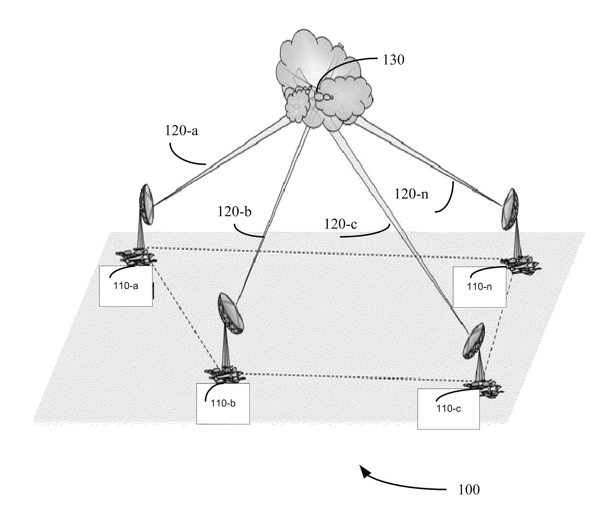
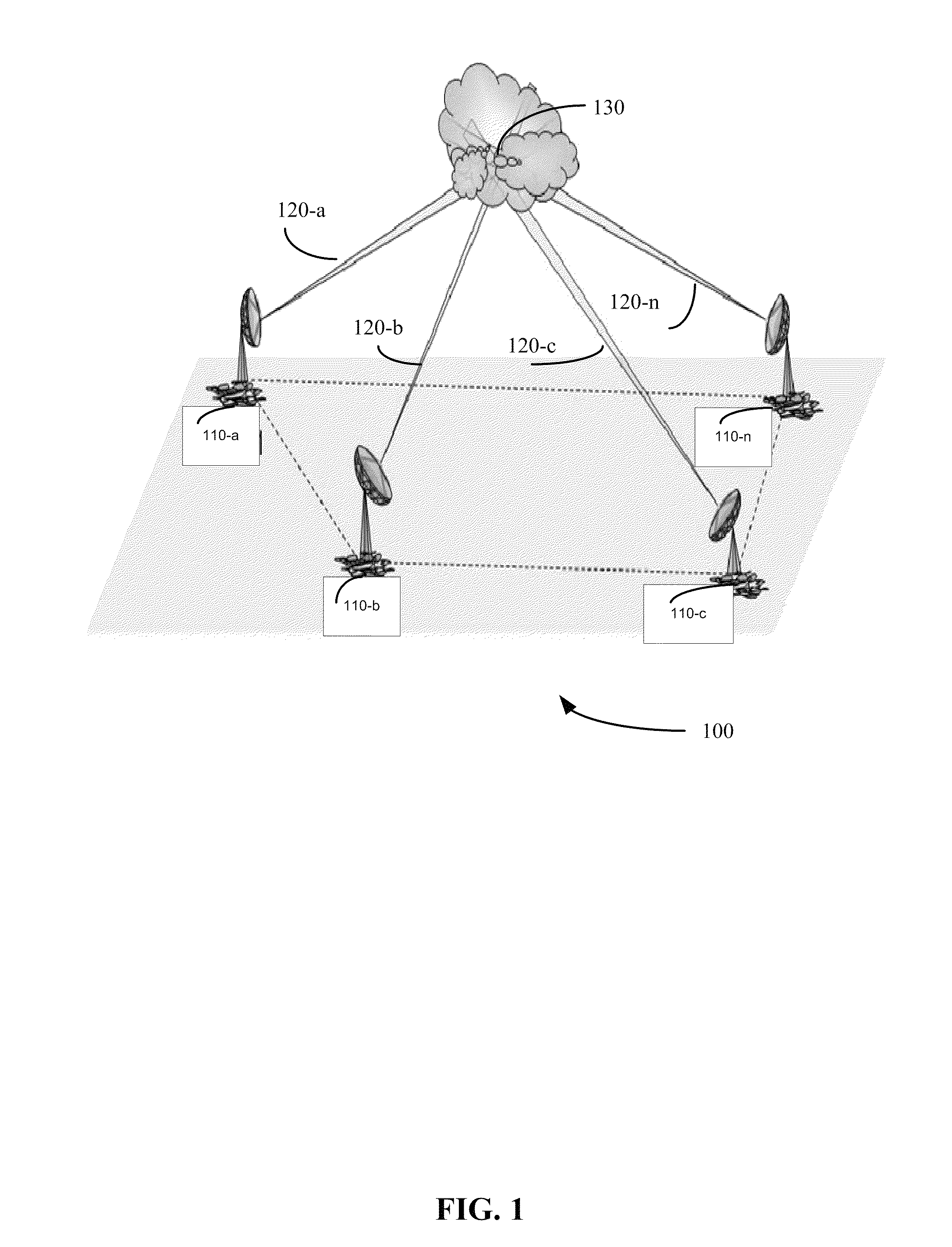
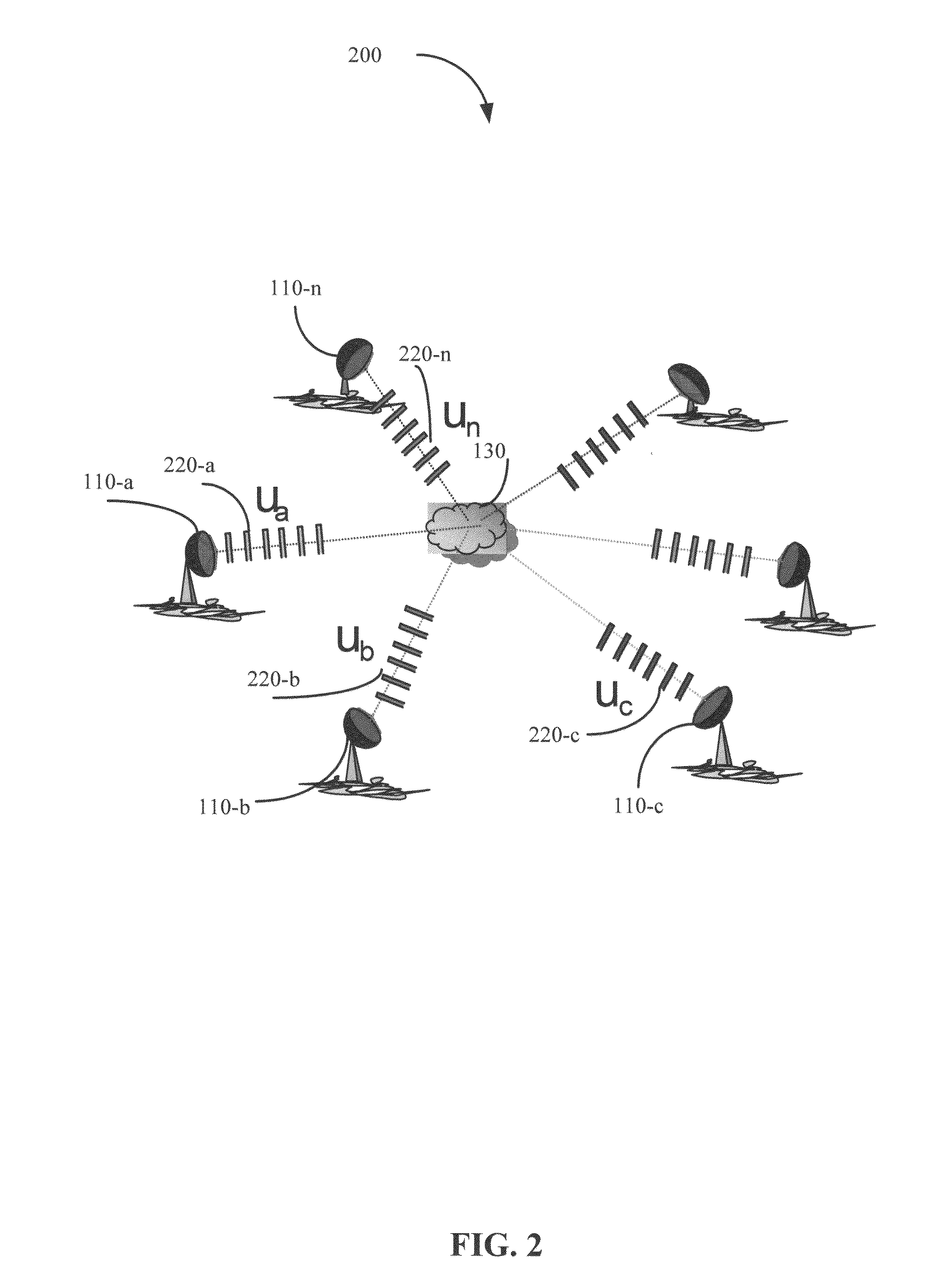
Networked waveform system
a waveform system and network technology, applied in the field of radar, can solve the problems that monostatic doppler radar transmitting pulses with uniform pulse repetition frequency may face a limitation on maximum unambiguous range and maximum unambiguous velocity
- Summary
- Abstract
- Description
- Claims
- Application Information
AI Technical Summary
Benefits of technology
Problems solved by technology
Method used
Image

Examples
Embodiment Construction
[0028]A monostatic Doppler radar transmitting with uniform pulse repetition frequency (“PRF”) may face a limitation on maximum unambiguous range (“ra”) and maximum unambiguous velocity (“va”) determined by pulse repetition frequency (“PRF”) and wavelength (“λ”). A maximum unambiguous range may be determined using an equation such as the following:
[0029]ra=c2×PRF
where c is the speed of light. PRF may be reciprocally related to a pulse repetition time (“PRT”). A maximum unambiguous velocity may be determined using an equation such as the following:
[0030]va=λ×PRF4
where va may be referred to as a Nyquist velocity. There may be a conflicting tradeoff between va and ra as their product is fixed for a given wavelength, represented by an equation such as the following:
[0031]va×ra=c×λ8.
[0032]This creates what is often called the range-Doppler dilemma. A PRF chosen to achieve large unambiguous range measurements may be a poor choice for achieving large unambiguous velocity measurements.
[0033]...
PUM
 Abstract
Description
Claims
Application Information