Target position identifying apparatus

a technology of positioning identifier and target position, which is applied in the field of positioning identifier, can solve the problems of deterioration in the precision of the maker center point detection, difficult detection of precision target position, and possible erroneous recognition, and achieves the effects of simple edge detection technique, improved detection reliability, and easy detection

Active Publication Date: 2011-12-13
AISIN SEIKI KK
View PDF17 Cites 2 Cited by
  • Summary
  • Abstract
  • Description
  • Claims
  • Application Information

AI Technical Summary

Benefits of technology

[0013]Further, in the characterizing feature of the target position identifying apparatus relating to the present invention, preferably, said first color is blue, said second color is red; and said luminance value, said first color component value and said second color component value are respectively a Y value, a Cb value and a Cr value in the YCbCr color representation system. As the Cb value (blue component) and the Cr value (red component) are in the extreme opposite relationship to each other, it becomes also possible to effect precision blue determination and red determination, from a difference between the Cb value and the Cr value. Also, since the YCbCr color representation system is often employed for video signals in a television broadcast etc., its processing devices can be readily and inexpensively available. Moreover, a target comprising the combination of blue and red is readily visually recognizable by humans. Hence, such target is convenient in this respect also.
[0014]According to a further preferred characterizing feature of the target position identifying apparatus relating to the present invention, said determination condition is variable in accordance with the luminance of the captured image or said luminance value in such a manner that a range for the color component value for determining that a pixel of the captured image belongs to either one of said color regions is narrowed in accordance with increase in the luminance of the captured image or said luminance value. If the luminance of the captured image or the luminance value is large or high, this means that the amount of light illuminating the target is large, so that the respective color difference component value too is large, but the noise component too can be larger at the same time. Therefore, by setting the determination condition (threshold) more strict, that is, by narrowing the range of color component value for determining that a pixel in the captured image belongs in either of the color regions, it is possible to eliminate noise. Conversely, if the luminance of the captured image or said luminance value is small or low, this means that the amount of light illuminating the target is small, so that the respective color difference component value too is small, but the noise component too can be small. Therefore, by setting the determination condition less strict, that is, by broadening the range of color component value for determining that a pixel in the captured image belongs in either of the color regions, detection of a particular color can be effected in more stable manner.
[0016]According to a further preferred characterizing feature of the target position identifying apparatus relating to the present invention, said target comprises a checkerboard pattern. A checkerboard pattern is created by repetition of rectangular faces having at least two different colors. Therefore, by choosing colors having significantly different pixel values for the different colors in the captured image, its pattern layout can be easily detected by a simple image processing operation, so that its detection reliability will improve. In particular, a border between different colors is detectable by a simple edge detecting technique. Hence, coordinates of a crossing point of a pair of borderlines of differing directions together delimiting the checkerboard pattern can be used as the target position advantageously. With this, a single point is calculated as the target position, thus realizing target position identification with high precision. In implementing this technique, if the position coordinates of the target are known in advance, the positional relationship relative to the camera on the captured image can be calculated. Hence, the target layout can be freely set.
[0017]According to a further preferred characterizing feature of the target position identifying apparatus relating to the present invention, the surface of the target is provided with matting treatment. With this, it is possible to restrict external disturbance on the captured image due to reflection of the illumination light, etc.
[0018]One preferred mode of application of the target position identifying apparatus relating to the present invention is calibration of the mounting position of a camera mounted on a vehicle. That is, as the captured image, there is employed an image captured by the vehicle-mounted camera and evaluation of the mounting position of the camera is effected based on the position of the target in the captured image calculated by the target position calculating section. In such mode of application, preferably, the target is formed by means of e.g. painting on the road or floor surface on which the vehicle travels. However, in this case, there is the possibility of the target being treaded upon by the wheels of the vehicle, so the recognition characteristics of the target may deteriorate. In order to restrict this problem, if the target is provided in the form of a pair of targets juxtaposed along the right / left direction of the vehicle, it is proposed to set these targets with a distance therebetween smaller than the tread width of the vehicles so that the right and left wheels of the vehicle may stride across the two targets. Or, it is proposed to set the targets with a distance therebetween greater than the tread width of the vehicles so that the vehicle may pass between the targets. For, these arrangements both reduce the possibility of the targets being treaded upon by the right and left wheels of the vehicle.

Problems solved by technology

However, depending on the condition of the illuminating light or sunlight, precision of detection of the edge of the white and black regions may become unstable, thus resulting in deterioration in the precision of the maker center point detection.
Therefore, with using color difference signals alone, precision target position detection is difficult.
Moreover, an erroneous recognition may occur when e.g. some object which looks similar to the pattern of the target is placed inadvertently within the view field of the camera.
To avoid this, troublesome management of the working environment will be needed.

Method used


Image

  • Target position identifying apparatus
  • Target position identifying apparatus
  • Target position identifying apparatus

Examples


Embodiment Construction

[0025]Next, embodiments of the present invention will be explained with reference to the accompanying drawings.

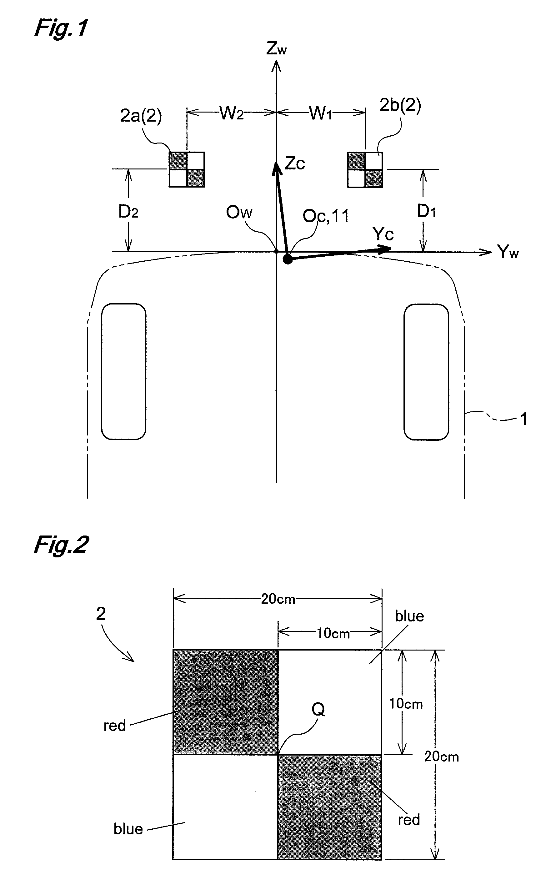
[0026]FIG. 1 is an explanatory diagram showing one example of layout relationship between calibration targets 2 (calibration indices) and a vehicle 1. A camera 11 (vehicle-mounted camera) is mounted upwardly of a rear number plate of the vehicle 1 with an amount of lateral offset relative to the longitudinal axis of the vehicle body and with an optical axis of the camera being oriented downwards (e.g. 30 degrees downward relative to the horizontal). Meanwhile, in this embodiment, the longitudinal axis of the vehicle body and the optical axis of the camera are not parallel with each other. The camera 11 is a wide-angle camera having a horizontal view angle of from 110 to 120° C. and is capable of capturing an image of an area extending about 8 meters rearward. This camera 11 is calibrated for absorbing mounting error or tolerance when it is mounted on the vehicle 1 in e.g. a...


PUM


Abstract

A target position identifying apparatus includes a color difference converting section for processing pixel values of an image of a target comprised of combination of a first color and a second color obtained from the target under influence of ambient light, thus generating a color component value of the first color, a color component value of the second color and a luminance value, a color region determining section for determining region of the first color and region of the second color, based on the first color component value and the second color component value, with using a determination condition based on either luminance of the captured image or the luminance value, a border detecting section for detecting border between the first color and the second color in the target based on result of the determination by the color region determining section and a target position calculating section for calculating the position of the target on the image based on result of the border detection by the border detecting section.

Description

TECHNICAL FIELD[0001]The present invention relates to a target position identifying apparatus for identifying a position of a target in a captured image through image processing of captured image data of the target comprising combination of a first color and a second color.BACKGROUND ART[0002]In recent years, there have been an ever increasing number of vehicles mounting a camera for allowing a driver of the vehicle to view e.g. a scene laterally or rearwardly of the vehicle on a monitor device provided inside the vehicle. Further, there has been developed an apparatus for assisting driving such as driving for parking by effecting e.g. image processing utilizing this camera's captured image. Especially, in the case of a camera configured to capture an image for use e.g. as a basis for generating information to be utilized for positioning of the vehicle, high precision is required in its calibration such as optical axis adjustment. The above-described target position identifying appa...

Claims


Application Information

Patent Timeline
Patent Type & Authority Patents(United States)
IPC IPC(8): H04N7/18
CPCG06T7/0018H04N17/002G06T2207/10024G06T7/80
Inventor NAKAMURA, YOSHIHIROYAMADA, ETSUOTAKAGI, KEIJICHIBA, MASATAKA
Owner AISIN SEIKI KK
Why Eureka
Try Eureka