
Radio communication apparatus and radio communication method

a radio communication and radio communication technology, applied in the field of radio communication apparatus and radio communication method, to achieve the effect of preventing the disconnection of on-going communication

Active Publication Date: 2011-12-13
KYOCERA CORP
View PDF11 Cites 0 Cited by
  • Summary
  • Abstract
  • Description
  • Claims
  • Application Information

AI Technical Summary

Benefits of technology

[0009]Then, the present invention has been made in consideration of a situation mentioned above. An objective of the present invention is to provide a radio communication apparatus and a radio communication method that can prevent an on-going communication from being disconnected at a time of a handover due to drop of an output voltage of a battery.
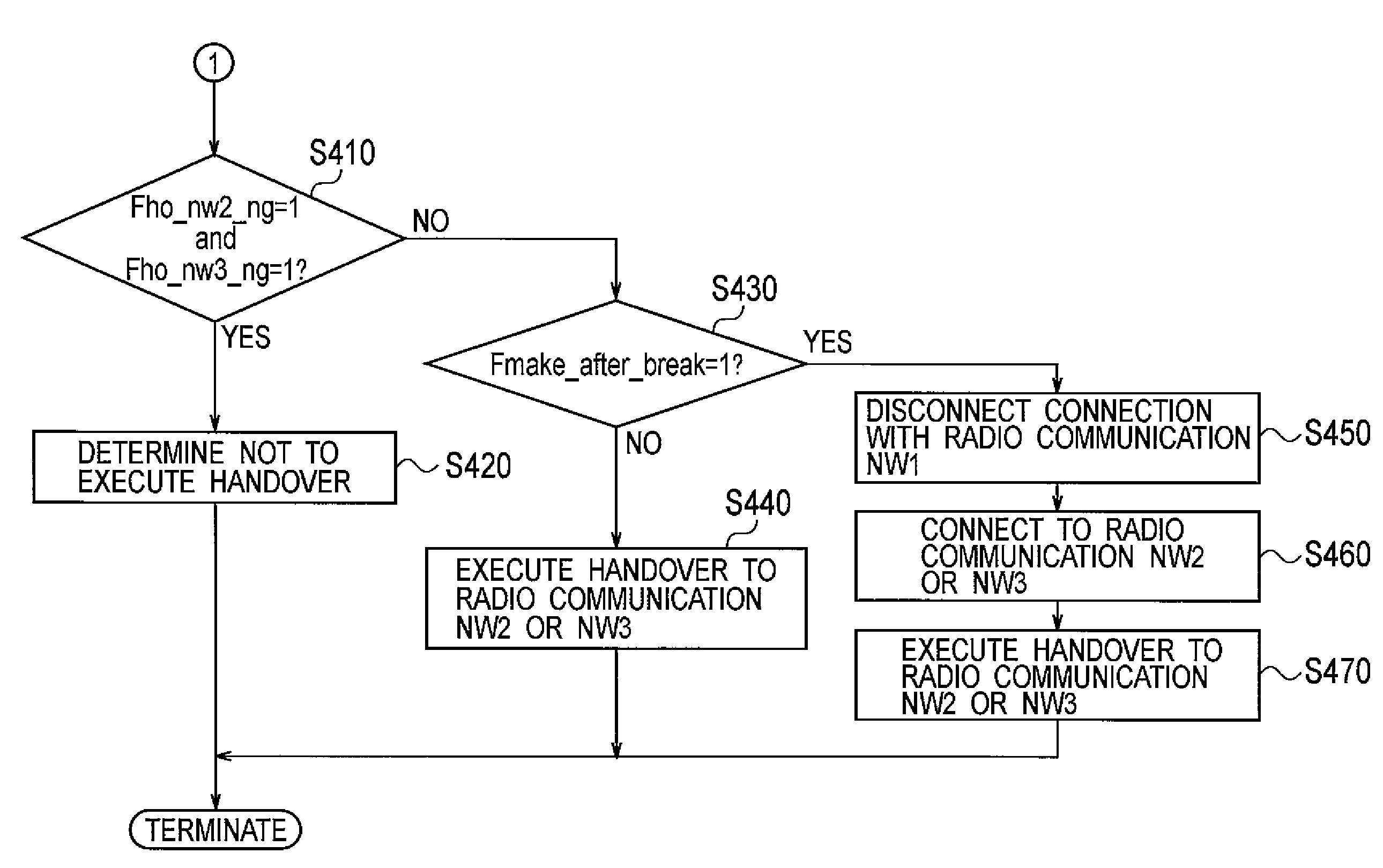
[0011]According to such a radio communication apparatus, a handover (for example, a soft handover) to the other radio communication network is stopped when the predicted voltage obtained by subtracting the dropped amount of the voltage from the associated output voltage is not more than the predetermined threshold, the voltage dropped with an execution of the handover. Accordingly, the disconnection of an on-going communication due to the output voltage dropped to a level which causes a protection circuit to operate can be prevented.
[0016]According to such a radio communication apparatus, a handover (for example, a soft handover) to the other radio communication network is stopped when the predicted voltage obtained by subtracting the dropped amount of the voltage from the associated output voltage is not more than the predetermined threshold, the voltage dropped with an execution of the handover. Accordingly, the disconnection of an on-going communication due to the output voltage dropped to a level which causes a protection circuit to operate can be prevented.
[0021]According to the aspects of the present invention, it is possible to provide a radio communication apparatus and a radio communication method which prevents an disconnection of an on-going communication at the time of handover due to a drop of an output voltage of a battery.

Problems solved by technology

However, the conventional radio communication apparatus mentioned above has the following problem.

Method used


Image

  • Radio communication apparatus and radio communication method
  • Radio communication apparatus and radio communication method
  • Radio communication apparatus and radio communication method

Examples


Embodiment Construction

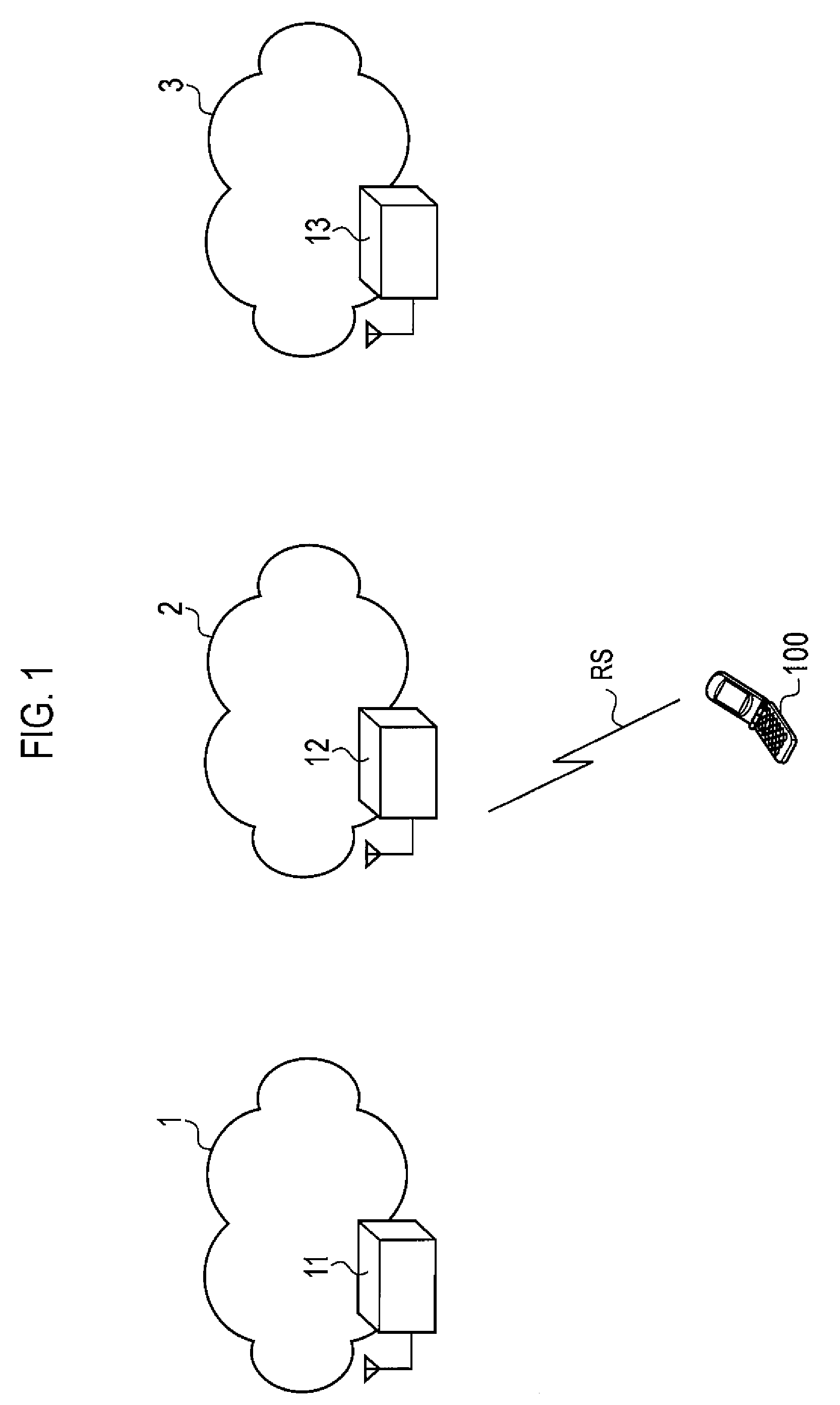
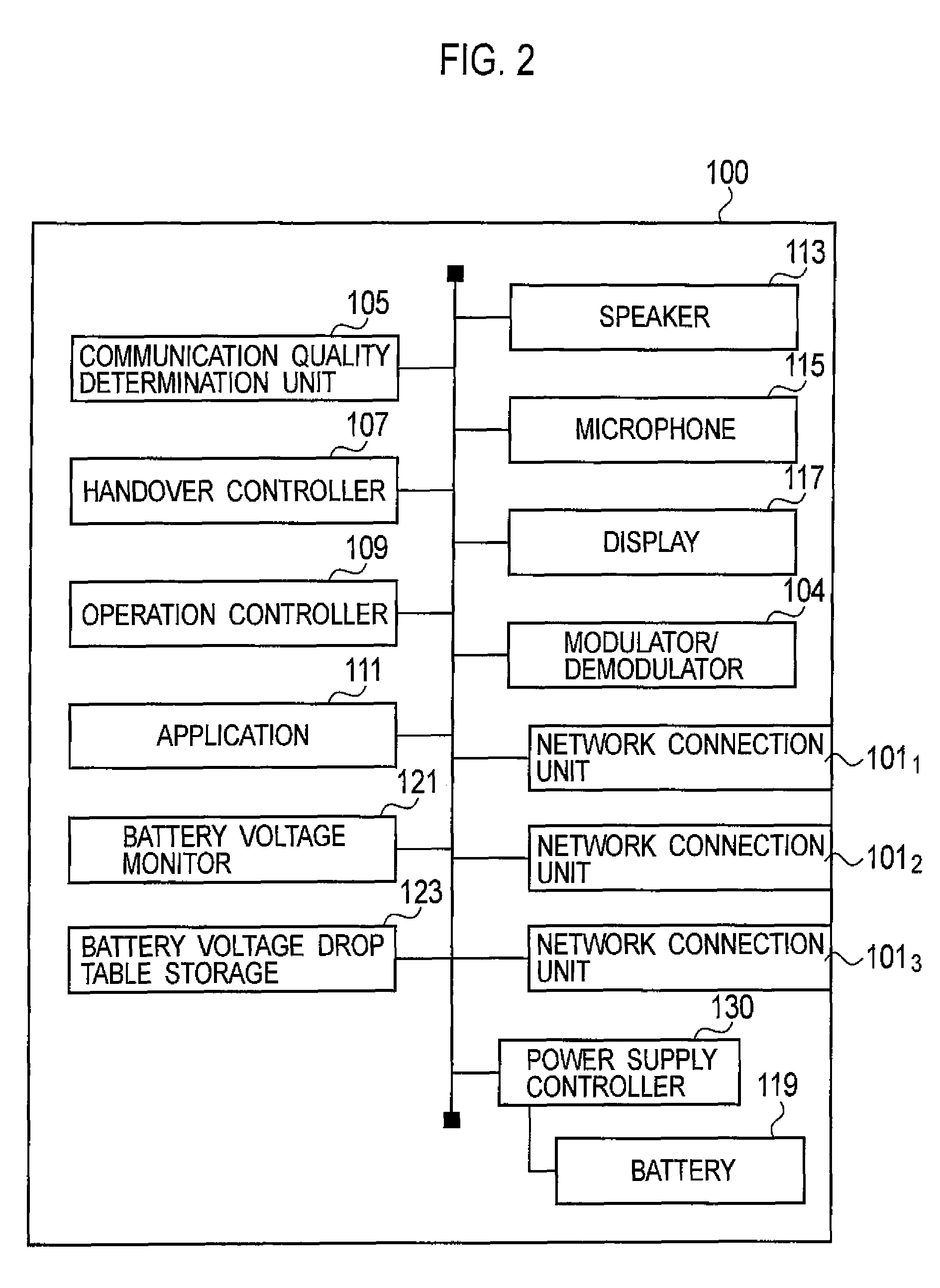
[0029]Next, an embodiment of the present invention will be described. Specifically, description will be given on (1) an overall schematic configuration of a communication network, (2) a functional block configuration of a radio communication apparatus, (3) operation of the radio communication apparatus, (4) effects and advantages, and (5) other embodiments.

[0030]Note that the same or similar portions are denoted by the same or similar reference numerals in the descriptions of the drawings below. It should be noted, however, that the drawings are schematic only, and that ratio of each dimension and the like differ from those in reality.

[0031]Accordingly, specific dimensions and the like should be determined in consideration of the descriptions below. In addition, some of the dimensional relations and ratios differ in the drawings as a matter of course.

(1) Overall Schematic Configuration of Communication Network

[0032]FIG. 1 is an overall schematic configuration diagram of a communicat...


PUM


Abstract

A radio communication apparatus includes a battery voltage monitor configured to acquire a dropped amount of an output voltage in a case where a network connection unit is connected to at least one of radio communication networks used in a handover; and an operation controller configured to stop a handover controller from executing the handover to the other radio communication network when a predicted voltage obtained by subtracting the dropped amount from the output voltage is not more than a predetermined threshold.

Description

CROSS REFERENCE TO RELATED APPLICATION[0001]This application is based upon and claims the benefit of priority from the prior Japanese Patent Applications No. P2008-18381 and P2008-18382, filed on Jan. 29, 2008; the entire contents of which are incorporated herein by reference.BACKGROUND OF THE INVENTION[0002]1. Field of the Invention[0003]The present invention relates to a radio communication apparatus that operates with a battery and is connectable to multiple radio communication networks, and also to a radio communication method used in the radio communication apparatus.[0004]2. Description of the Related Art[0005]In recent years, along with advancement of radio communication technologies, radio communication apparatuses connectable to multiple radio communication networks employing different communication schemes have been proposed. Such a radio communication apparatus (for example, mobile communication terminal) connectable to multiple radio communication networks generally oper...

Claims


Application Information

Patent Timeline
Patent Type & Authority Patents(United States)
IPC IPC(8): H04W36/00
CPCH04W36/36H04W52/0277Y02D30/70H04B1/40
Inventor YOKOTA, TOMOYOSHIMIKI, TOMOHIRO
Owner KYOCERA CORP
Learn More