

Yarn testing apparatus
a testing apparatus and a technology of a test tube, applied in the direction of the apparatus for force/torque/work measurement, the measurement device, the measurement of tension, etc., can solve the problems of affecting the function of the measuring element, affecting the movement of mechanical parts, and accumulating dust and dir
- Summary
- Abstract
- Description
- Claims
- Application Information
AI Technical Summary
Benefits of technology
Problems solved by technology
Method used
Image

Examples
Embodiment Construction
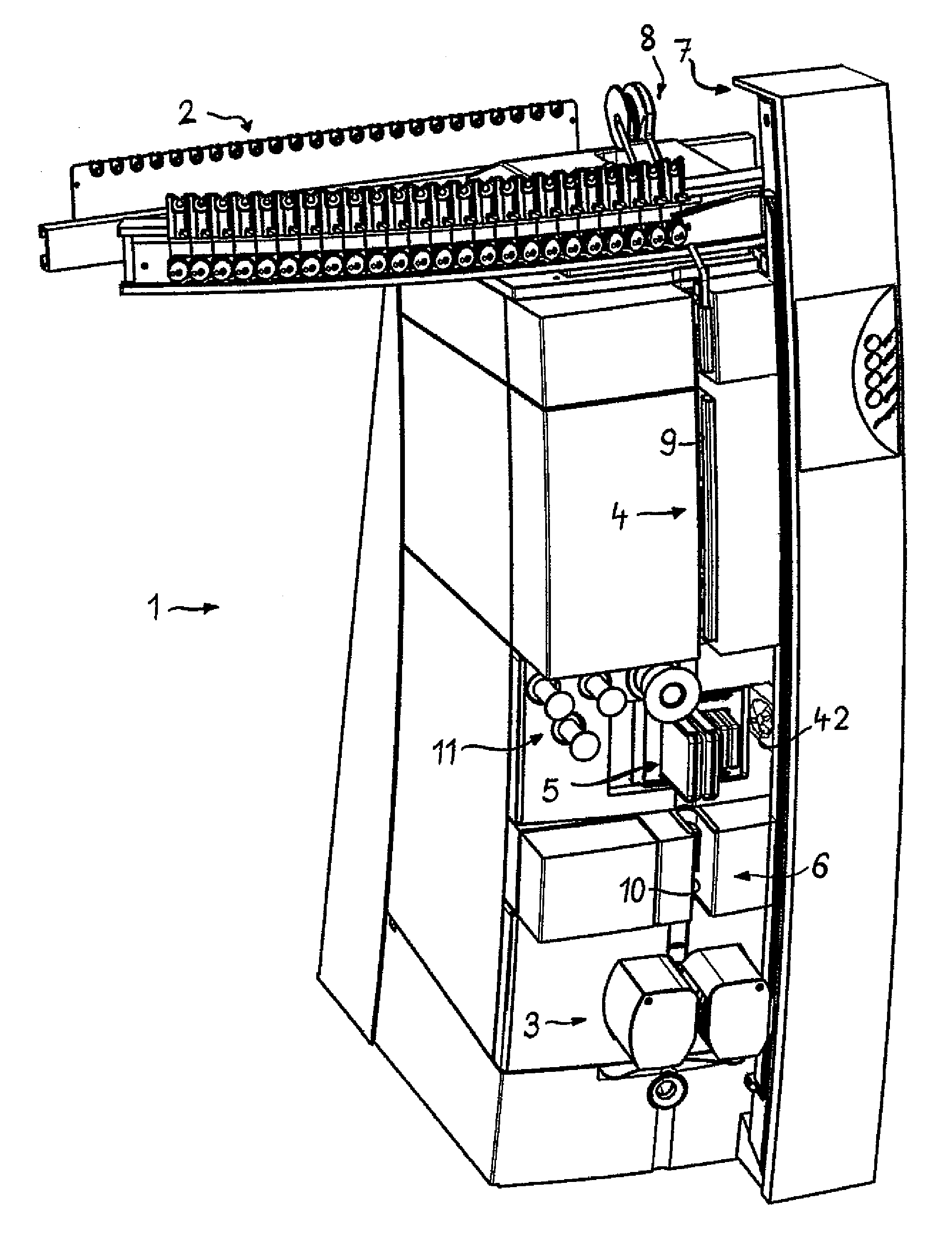
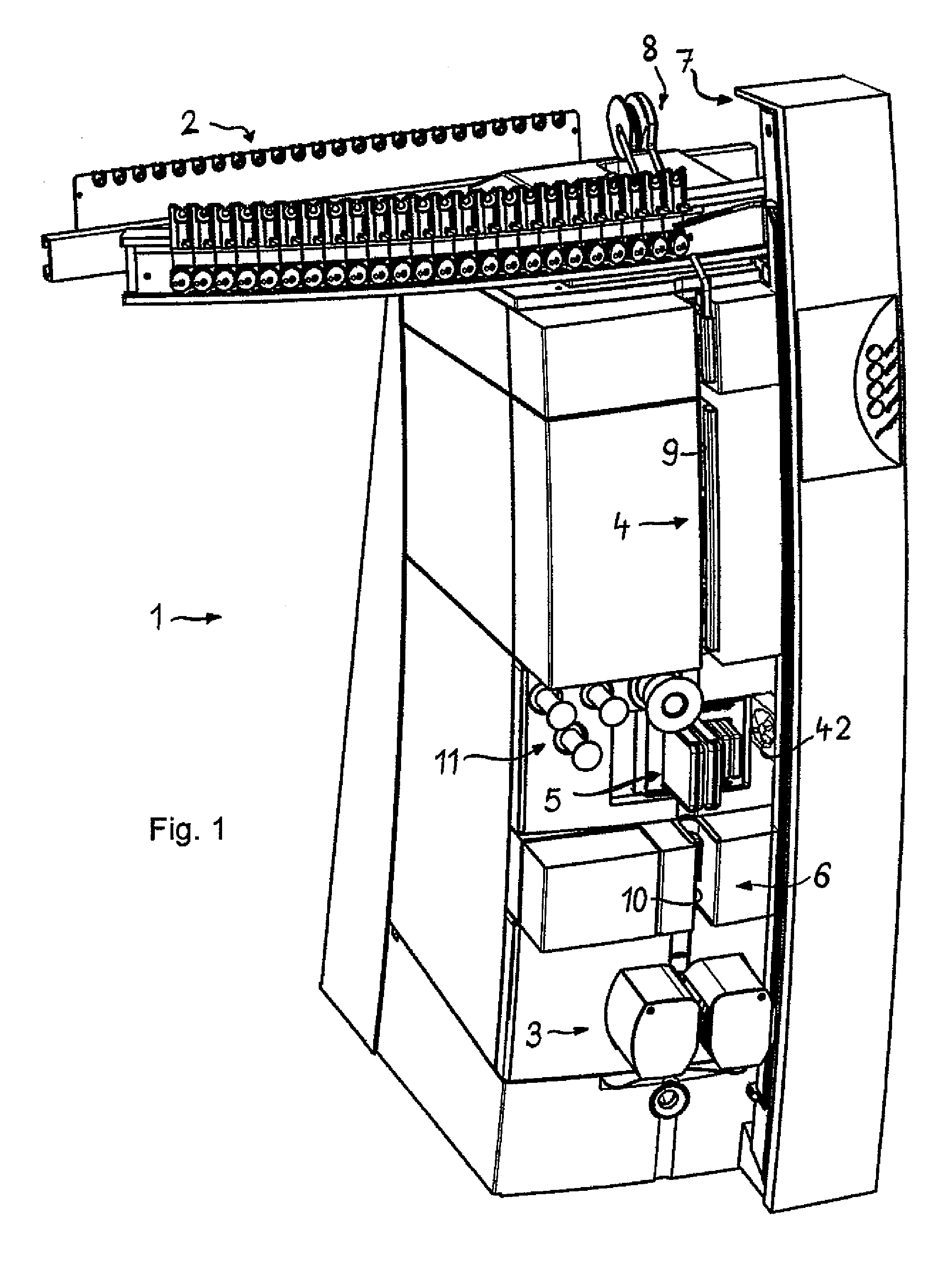
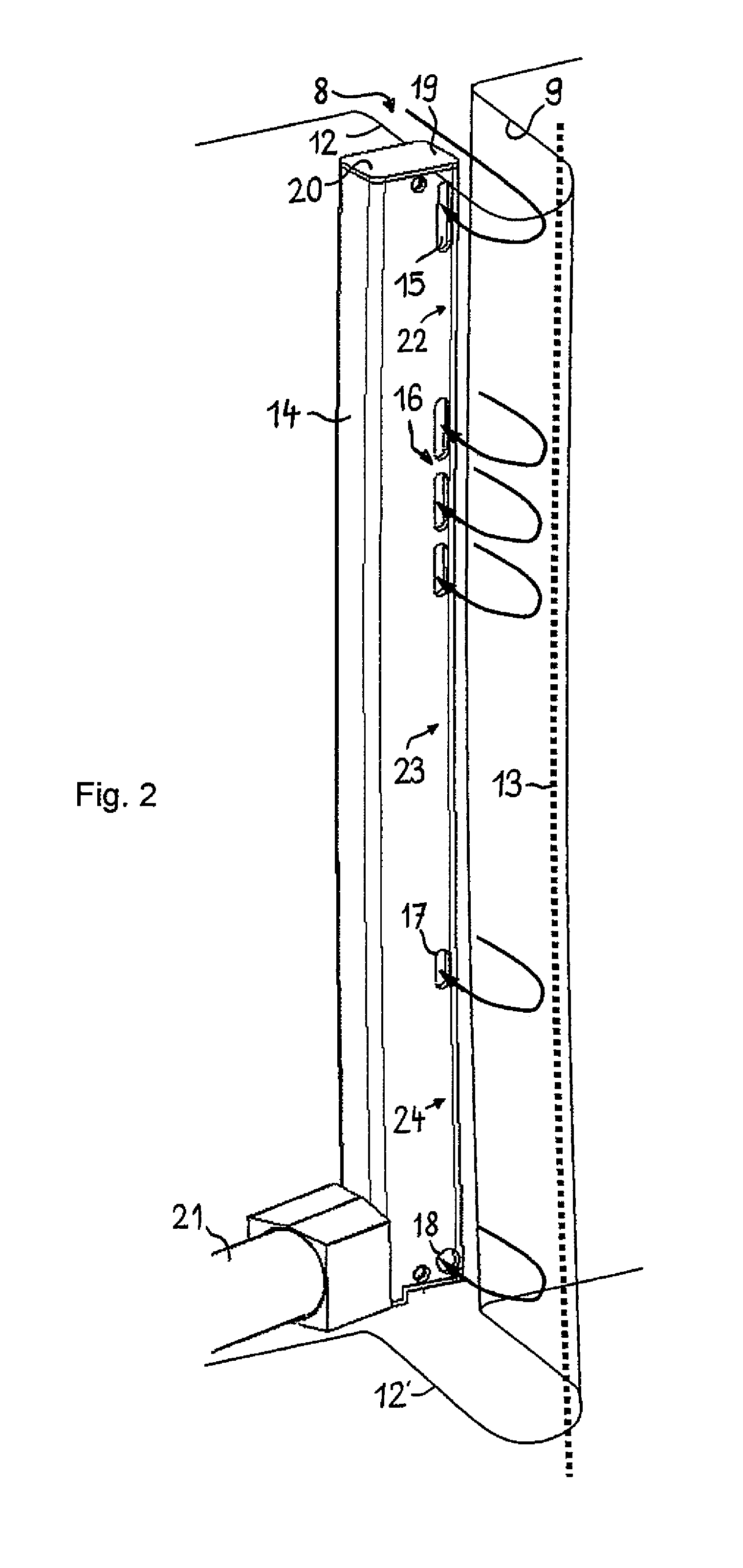
[0007]A device of the type mentioned, which does not have the drawbacks mentioned and which reduces the depositing of loose fibres and dust and dirt particles, is now to be proposed by the invention. Furthermore, a corresponding method for removing undesired particles, such as loose fibres, dirt or dust from a device for the automatic determination of characteristics on textile test material is to be disclosed.
[0008]This and other objects are achieved by the device and the method as defined in the independent claims. Advantageous embodiments are disclosed in the dependent claims.
[0009]At least one point along a path or a track, which the test material traverses, the invention provides means for removing undesired particles, which originate from the test material itself or which are entrained by the test material. The means for removing undesired particles contain a plurality of suction elements, which are arranged along the path and spaced apart from one another and are suitable for...
PUM
| Property | Measurement | Unit |
|---|---|---|
| speed | aaaaa | aaaaa |
| speed | aaaaa | aaaaa |
| speed | aaaaa | aaaaa |
Abstract
Description
Claims
Application Information