Rotational component torque measurement and monitoring system

a technology of rotational components and torque measurement, applied in the field of monitoring systems, can solve the problems of not being able to bridge the gap in some of the most critical applications, not being able to achieve non-contact measurement, and being particularly difficult to achiev

Active Publication Date: 2011-12-20
INT ELECTRONICS MACHINES
View PDF6 Cites 34 Cited by
  • Summary
  • Abstract
  • Description
  • Claims
  • Application Information

AI Technical Summary

Problems solved by technology

This is particularly difficult when it is in relation to rotating equipment components in challenging environments.
Many incumbent technologies exist that partially fulfill monitoring capabilities but fail to bridge the gap in some of the most critical applications.
Non-contact measurement is often required where optical or other established methods have significant limitations.
A robust characterization method that is tolerant to relative movement and has minimum interference clearance that can be attached to high speed rotating parts with negligible impact to dynamic balance of the rotating members is lacking in current product offerings in the market place.

Method used


Image

  • Rotational component torque measurement and monitoring system
  • Rotational component torque measurement and monitoring system
  • Rotational component torque measurement and monitoring system

Examples


examples of other embodiments

[0049]The use of this invention is not limited to only severe environments or only where component movement precludes use of existing technologies. This method is applicable to any rotational element where there is a desire to determine strain of that element. Use to measure linear or rotational movement is possible but the greatest value lies in the rotary applications. Following are some examples of other embodiments.

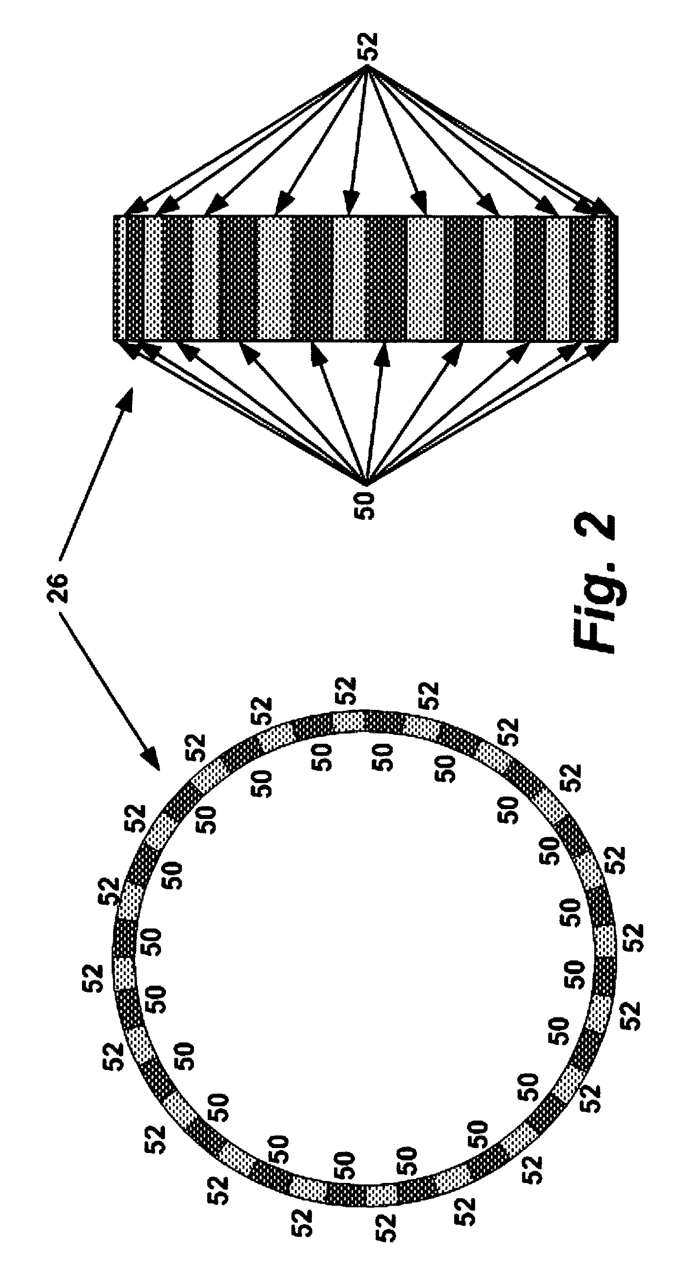
[0050]In one alternate embodiment, more than one ring-coil pair is present at each end of a shaft 22. One reason to have more than one would be if the flexible magnetic rings discussed earlier are used. By having two rings 26 on each end, each offset slightly from the other by some offset distance 122, one ensures that all portions of the rotation of the shaft have at least one ring-pair on each end with a non-discontinuous signal; that is, the seam 120 discontinuity in each ring is “covered for” by the other ring. This ensures that there are no physical “blind spots”...


PUM

PropertyMeasurementUnit
torqueaaaaaaaaaa
circumferenceaaaaaaaaaa
magnetic fieldaaaaaaaaaa

Abstract

A system and method for measuring torque on a rotating component, comprising of signal-producing components which are applied to the rotating component, and a means for obtaining the signals produced by said signal producing components, in which at least two signal producing components are applied to the rotating component with some linear separation between the two signal producing components and their corresponding devices for obtaining signals produced, such that torque applied to the rotating component will cause a change in phase between the signals received from each of the signal-producing components and thus permit the measurement of torque based on this change in phase; one embodiment of this invention comprising two magnetic rings, one at either end of a driveshaft, with sensor coils placed near to each magnetic ring such that an alternating electrical current is produced, the comparative phase between these currents permitting measurement of torque on the driveshaft.

Description

REFERENCE TO PRIOR APPLICATIONS[0001]The current application claims the benefit of U.S. Provisional Application No. 61 / 071,862, titled “Rotational Component Torque Measurement and Monitoring System”, which was filed on 22 May 2008, and which is hereby incorporated by reference.GOVERNMENT LICENSE RIGHTS[0002]The U.S. Government has a paid-up license in this invention and the right in limited circumstances to require the patent owner to license others on reasonable terms as provided for by the terms of Contract W911W6-05-C-0008 awarded by the United States Army.TECHNICAL FIELD[0003]The disclosure relates generally to monitoring systems, and more particularly, to a new and improved method for measuring torque.BACKGROUND ART[0004]Measurement of torque and related parameters are extremely important capabilities in a number of transportation and industrial applications. Measuring the torque or strain on a mechanical element such as a drive shaft can be used in HUMS (Health and Usage Monit...

Claims


Application Information

Patent Timeline
Patent Type & Authority Patents(United States)
IPC IPC(8): G01L3/02
CPCG01L3/109G01L3/104
Inventor MIAN, ZAHIDPEABODY, WILLIAMSALON, SHEPPARD
Owner INT ELECTRONICS MACHINES
Why Eureka
Try Eureka