Electric vehicle

a technology for electric vehicles and electric components, applied in the field of electric vehicles, can solve the problems of high cost of electromagnetic shield paint, adversely affecting various types of electric components mounted on the vehicle body, and requiring a lot of time and expense, and achieve the effect of simple and easy manner

Active Publication Date: 2011-12-20
MITSUBISHI MOTORS CORP
View PDF37 Cites 78 Cited by
  • Summary
  • Abstract
  • Description
  • Claims
  • Application Information

AI Technical Summary

Benefits of technology

[0009]The present invention provides an electric vehicle in which a battery unit mounted on the vehicle body can be shielded against an electromagnetic wave in a relatively simple and easy manner.
[0011]According to the present invention, it is possible to prevent electric components contained in the battery unit and the like arranged under the floor panel of the electric vehicle from being adversely affected by an electromagnetic wave. Further, it is also possible to prevent an electromagnetic wave generated from the battery unit from adversely affecting the neighboring electric components and the like.

Problems solved by technology

There is the possibility of the electromagnetic wave generated in the electric vehicle adversely affecting various types of electric components mounted on the vehicle body.
When electromagnetic shield paint is applied to the surface or the like of the battery case, as in the case of this prior art technique, a process for applying the paint, process for drying the applied paint, and the like are required, in addition to that the paint for electromagnetic shield itself is expensive.
For this reason, the electromagnetic shield means not only takes a lot of time, but also requires great expenses.
However, providing a conductive member in the small space inside the battery case is not desirable because a factor for causing an electric short circuit is provided.

Method used


Image

  • Electric vehicle
  • Electric vehicle
  • Electric vehicle

Examples


Embodiment Construction

[0024]An embodiment of the present invention will be described below with reference to FIGS. 1 to 7.

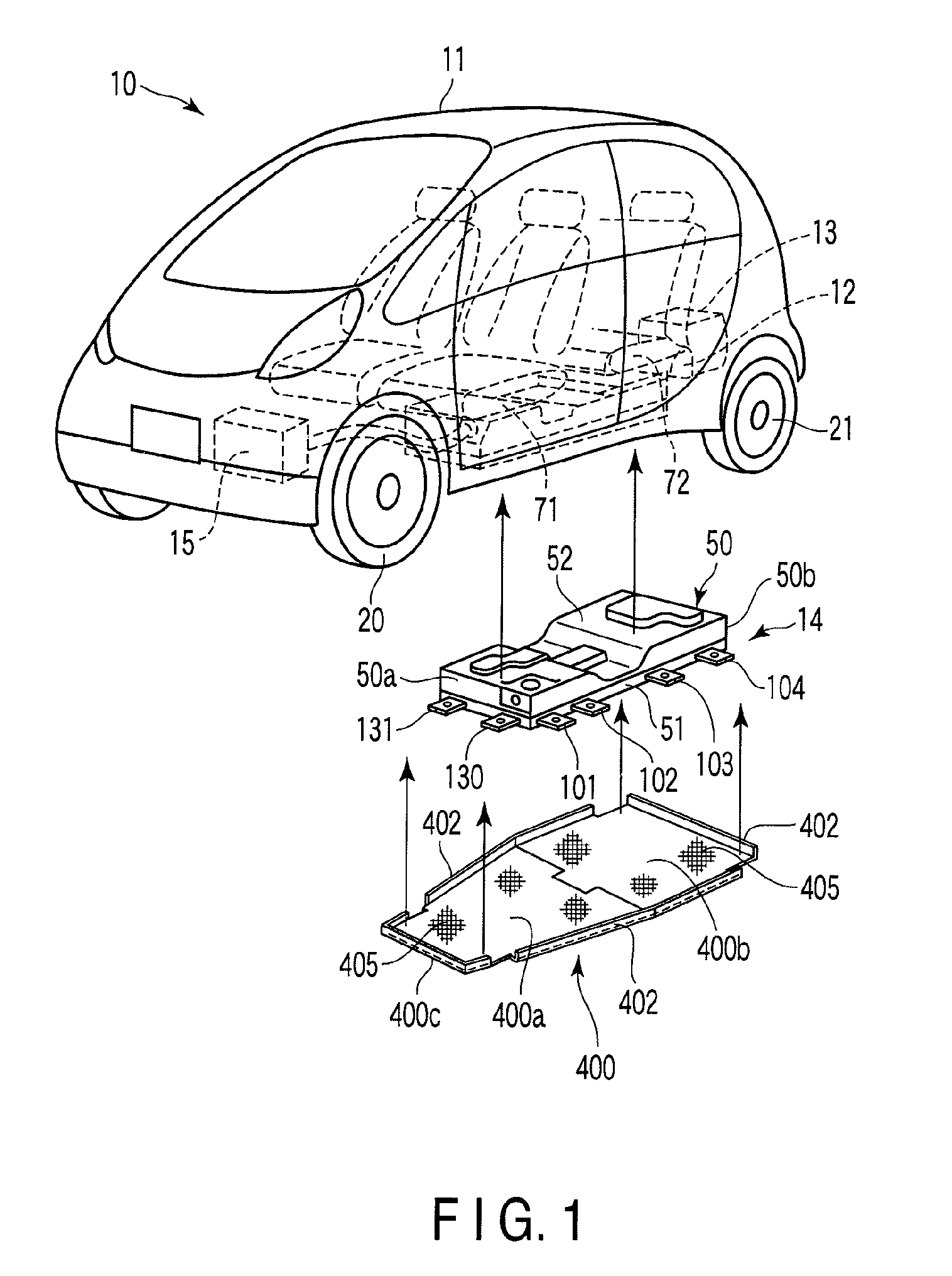
[0025]FIG. 1 shows an example of an electric vehicle 10. This electric vehicle 10 is provided with a motor 12 for traveling, and charging equipment 13 which are arranged at the rear part of a vehicle body 11, a battery unit 14 arranged under the floor of the vehicle body 11, and the like. A heat exchanger unit 15 for air-conditioning is arranged at the front part of the vehicle body 11.

[0026]Front wheels 20 of the vehicle 10 are supported by the vehicle body 11 by means of front suspensions (not shown). Rear wheels 21 are supported by the vehicle body 11 by means of rear suspensions (not shown). An example of the rear suspension is a trailing arm type rear suspension.

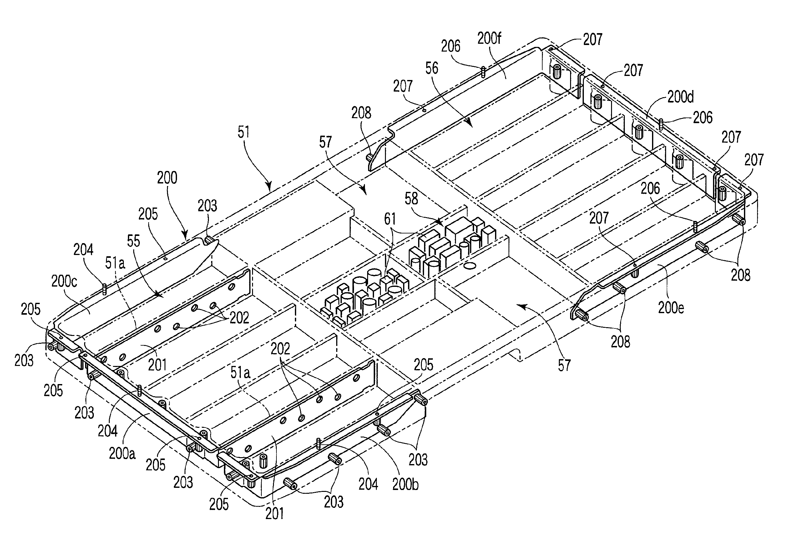
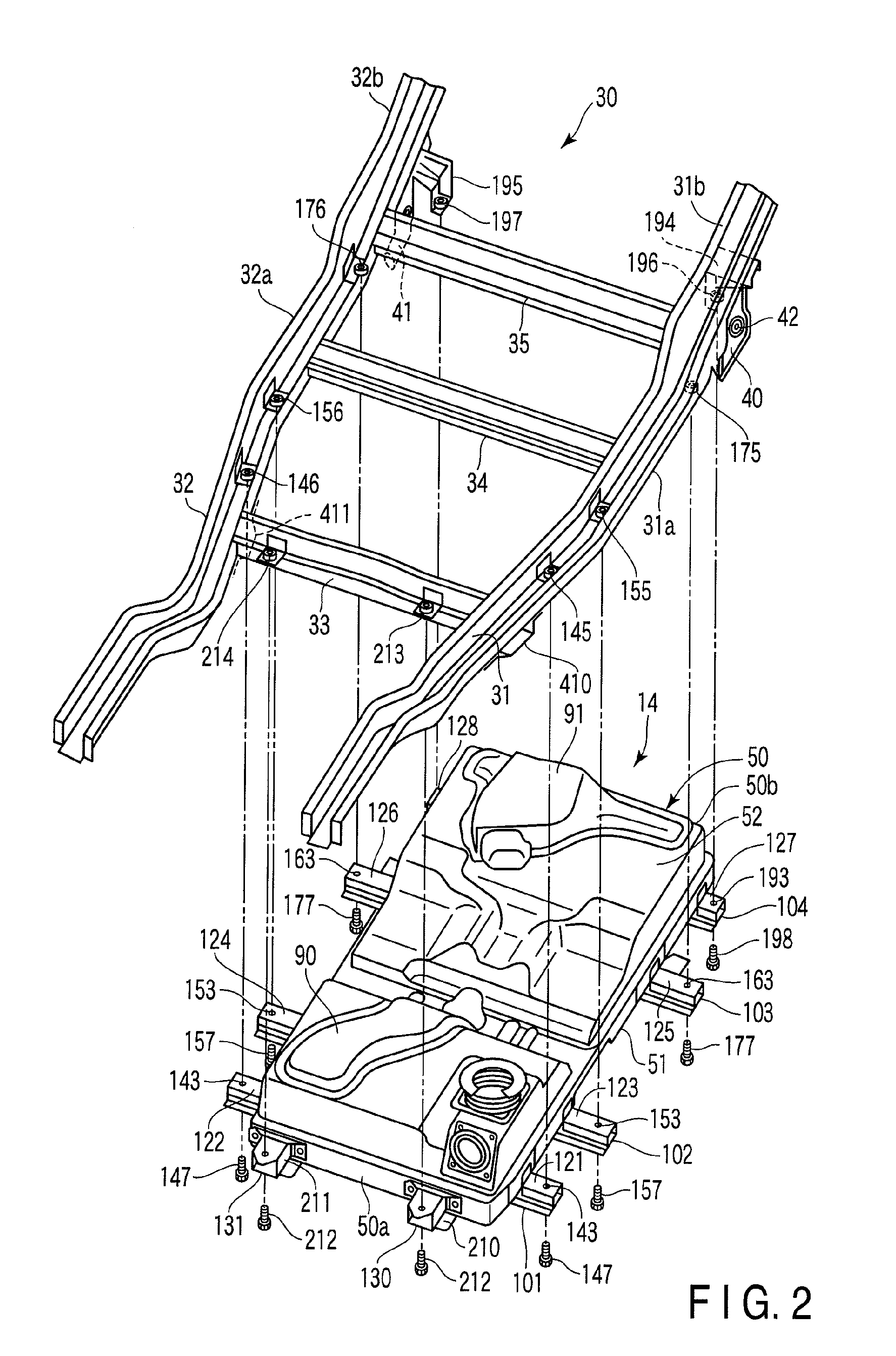
[0027]FIG. 2 shows a frame structure 30 constituting a lower skeletal structure of the vehicle body 11, and the battery unit 14 to be attached to the frame structure 30.

[0028]The frame structure 30 includes a pair of righ...


PUM

PropertyMeasurementUnit
widthaaaaaaaaaa
electromagneticaaaaaaaaaa
skeletal structureaaaaaaaaaa

Abstract

A battery unit is provided under a floor panel. The battery unit is arranged between a pair of right and left side members. The battery unit is provided with a battery case. The battery case includes a tray member and cover member. Electric components are contained in the battery case. Beam members made of metal are attached to the tray member. Both end portions of these beam members are supported by the side members. The tray member includes a resin and insert members made of metal provided inside the resin. The insert members include metal plates arranged on the front side and rear side of the electric components.

Description

CROSS REFERENCE TO RELATED APPLICATIONS[0001]This is a continuation Application of PCT Application No. PCT / JP2008 / 053995, filed Mar. 5, 2008, which was published under PCT Article 21(2) in Japanese.[0002]This application is based upon and claims the benefit of priority from prior Japanese Patent Application No. 2007-254261, filed Sep. 28, 2007, the entire contents of which are incorporated herein by reference.BACKGROUND OF THE INVENTION[0003]1. Field of the Invention[0004]The present invention relates to an electric vehicle which runs by means of a motor using a battery as a power source.[0005]2. Description of the Related Art[0006]It is known that in an electric vehicle using a battery as a power source, an electromagnetic wave is generated from, for example, the motor, current control circuit or the like. There is the possibility of the electromagnetic wave generated in the electric vehicle adversely affecting various types of electric components mounted on the vehicle body. For t...

Claims


Application Information

Patent Timeline
Patent Type & Authority Patents(United States)
IPC IPC(8): B60R16/04H01M50/202H01M50/244H01M50/249
CPCB60K1/04H05K9/002H01M2/1083H01M2/1077B60K2001/0438B60L50/66B60L50/64Y02T10/70Y02E60/10H01M50/249H01M50/202H01M50/244
Inventor TAKASAKI, SEIICHIFUJITA, KEINISHINO, HARUCHIKA
Owner MITSUBISHI MOTORS CORP
Why Eureka
Try Eureka