Tool for removing and tightening screw-on drains

a screw-on drain and tool technology, applied in the field of tools for removing and tightening screw-on drains, can solve the problems of difficult use of tools, difficulty in removing the screw-on flange for repair or replacement, and insufficient structural rigidity of spokes or arms to remove the flange, etc., to achieve the effect of simple and inexpensive manufacturing, simple design and easy removal

Active Publication Date: 2006-04-11
RECTORSEAL LLC
View PDF24 Cites 15 Cited by
  • Summary
  • Abstract
  • Description
  • Claims
  • Application Information

AI Technical Summary

Benefits of technology

[0014]Advantages of the present invention include the ability of the tool to be used with any of the various different size and type of drain flanges while using only two different cams or a modified cam. The design is very elegant because it is simple and inexpensive to manufacture while providing the strength and durability to remove and tighten the various types and sizes of screw-on drain flanges. The design allows easy and quick replacement of a cam so that the tool can be used with various sizes and designs of drain assembly flanges. The embodiments disclosed can be used for removal of bathtub assembly flanges which requires a high degree of strength and durability, as well as the tightening of the bathtub assemblies which requires that the surface of the flange not be marred. The design also allows the cam to be easily replaced with at least one other size cam to fit various size drain flange assemblies in a simple and easy manner. At least one embodiment utilizes a releasable driver that is releaseably engaged in the main body of the tool. Embodiments are disclosed that include a socket receptacle on the driver so that socket ratchets or breaker bars can be used, as well as extensions and other common tool pieces. In addition, power tools such as power drills, can be used with the present invention.

Problems solved by technology

After the drain assembly has been in place for a period of time, it can be very difficult to remove the screw-on flange for repair or replacement.
Because of the large force required to remove these drain flanges, the spokes or arms do not normally provide enough structural rigidity to remove the drain flange.
Typically, these tools are quite complex and difficult to use.
Currently existing tools are unable to be used with all of the different designs and sizes of the various screw-on drains.

Method used


Image

  • Tool for removing and tightening screw-on drains
  • Tool for removing and tightening screw-on drains
  • Tool for removing and tightening screw-on drains

Examples


Embodiment Construction

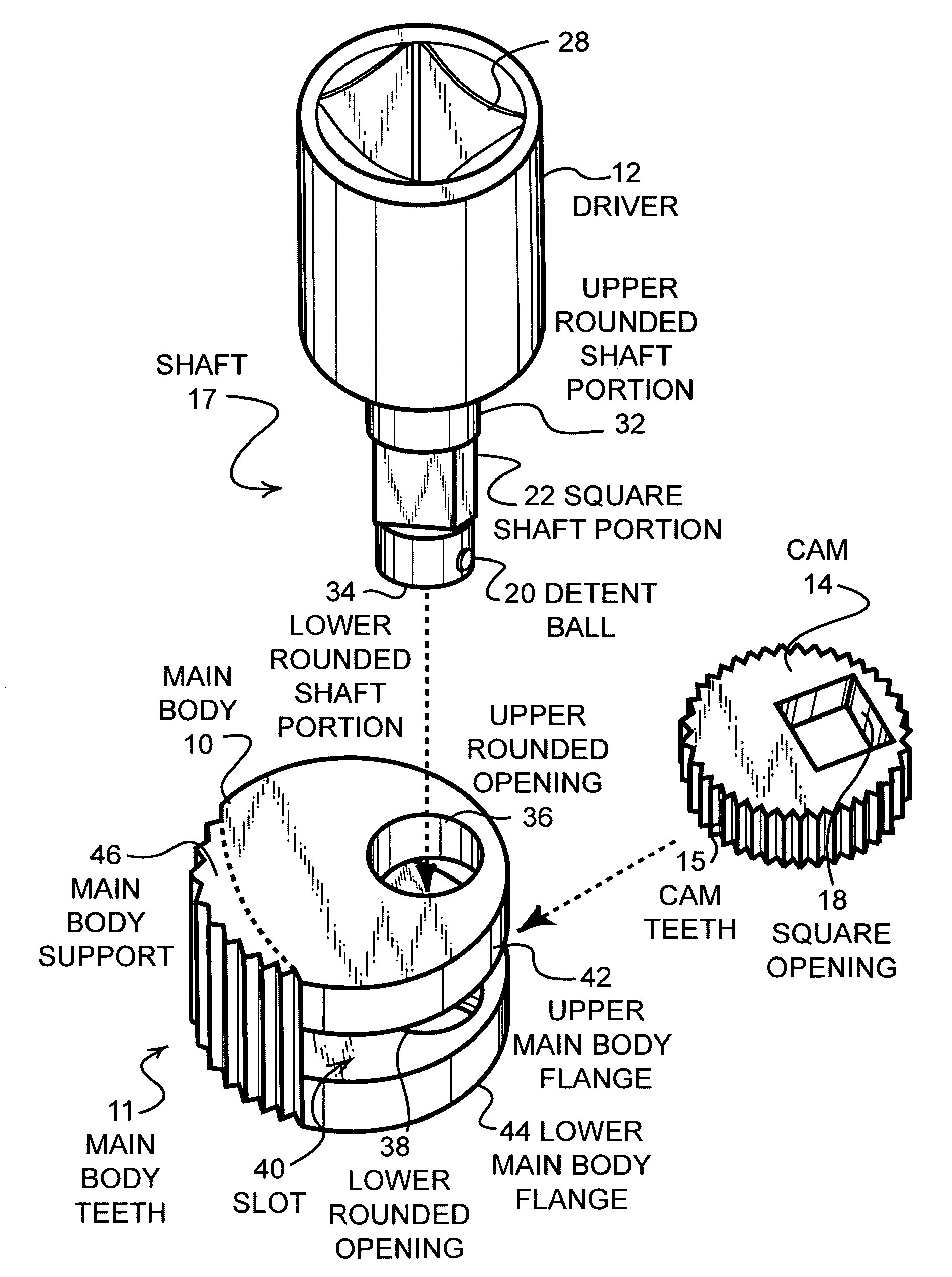
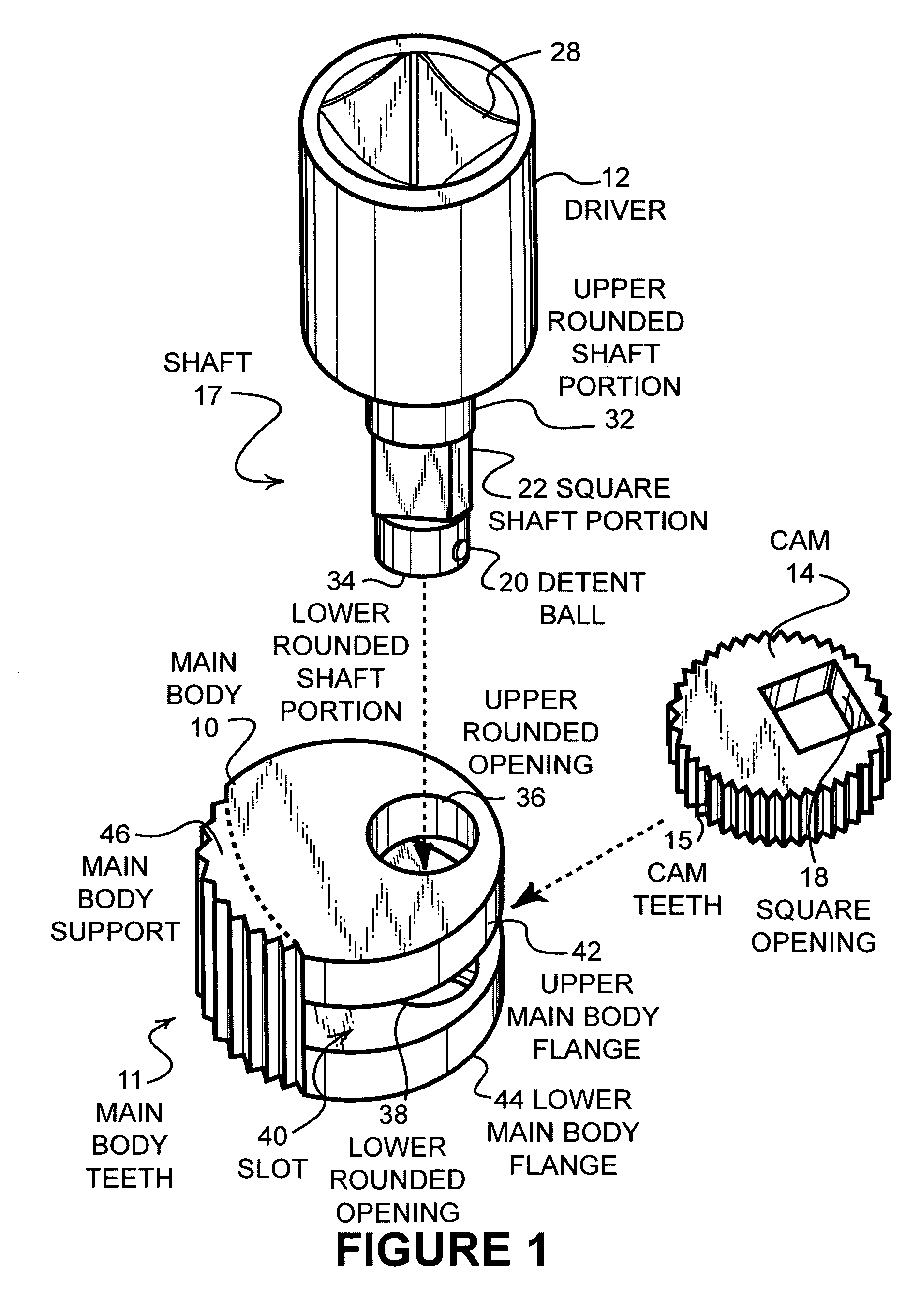
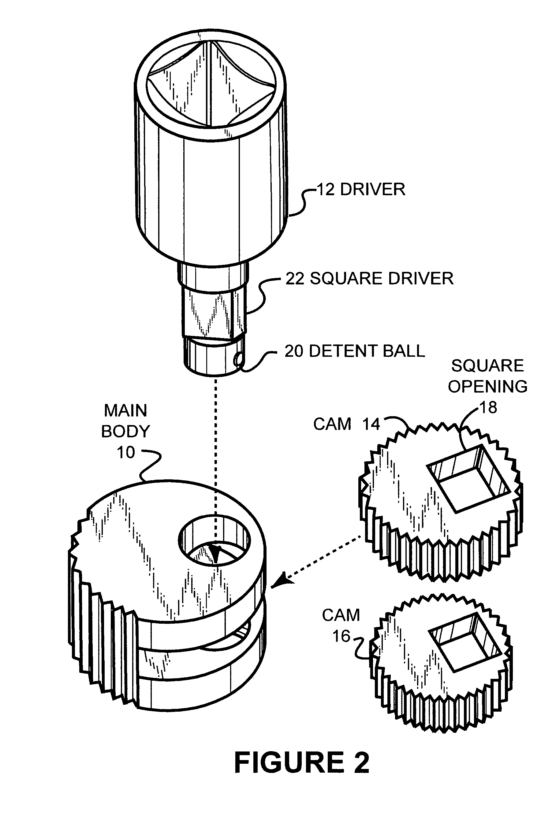
[0057]FIG. 1 is an isometric assembly view of three pieces of one embodiment of the present invention. The three primary pieces of this embodiment comprise the main body portion 10, the driver 12 and the cam 14. The main body portion 10 has teeth 11 formed therein along the outer sidewall portions adjacent the main body support 46. The main body portion has an upper main body flange 42 and a lower main body flange 44 that are connected by the main body support 46. As such, a slot 40 is formed between the upper main body flange 42 and the lower main body flange 44. The upper main body flange 42 has an upper rounded opening 36 formed therein which is in alignment with a lower rounded opening 38. The upper rounded opening 36 has a diameter that is larger than the lower rounded opening 38.

[0058]The driver 12 includes a socket portion 28 and a shaft 17. The shaft 17 has an upper rounded shaft portion 32, a square shaft portion 22, and a lower rounded shaft portion 34. The upper rounded s...


PUM

PropertyMeasurementUnit
angleaaaaaaaaaa
diameteraaaaaaaaaa
thicknessaaaaaaaaaa

Abstract

Disclosed is a tool for both removing and tightening screw-on drains that is simple and easy to use, has a simple design and is easy to manufacture. The tool is capable of engaging an inner surface of a drain flange in a manner that is sufficient to transfer enough force to remove screw-on drain flanges and is capable of use with various designs and sizes of screw-on drain flanges. Different size cams and different lever arms used on the cams allow the tool to optimize the radial force to torque ratio for both removal and insertion of screw-on drain flanges. In addition, nubs are used at the bottom of the drain flange to engage arms that typically are used on drain flanges to further add to the resistance that can be provided between the tool and the drain flange and distribute forces in a dynamic, instantaneous and automatic fashion to optimize removal of the drain flange.

Description

CROSS REFERENCE TO RELATED APPLICATIONS[0001]This application is based upon and claims the benefit of U.S. Provisional Patent Application 60 / 473,816 entitled “Tool for Removing and Tightening Screw-On Drains” filed May 27, 2003, and U.S. Provisional Patent Application 60 / 569,212 entitled “Tool for Removing and Tightening Screw-On Drains” filed May 7, 2004. The entire contents of both are hereby incorporated by reference for all that they disclose and teach.BACKGROUND OF THE INVENTION[0002]a. Field of the Invention[0003]The present invention pertains generally to plumbing and more particularly to a tool for removing and tightening screw-on drains.[0004]b. Description of the Background[0005]Screw-on drains are typically used in bathtubs and other applications such as utility sinks and other types of sinks or liquid retainers. The drain normally consists of a screw-on flange, commonly referred to as a bathtub shoe, that is threaded with male threads, and that is inserted through the to...

Claims


Application Information

Patent Timeline
Patent Type & Authority Patents(United States)
IPC IPC(8): B25B23/08B25B23/10B25B13/48B25B13/50
CPCB25B13/48B25B13/5083Y10T29/49822Y10T29/53683
Inventor WERNER, GARY D.JOHNSON, STEVEN X.
Owner RECTORSEAL LLC
Why Eureka
Try Eureka